An optical attenuator, or fiber optic attenuator, is a device used to reduce the power level of an optical signal, either in free space or in an optical fiber. The optical attenuators can have a tuning control to set the level of attenuation into a range of selectable values (variable optical attenuators), or can introduce a fixed level of attenuation (fixed optical attenuators).
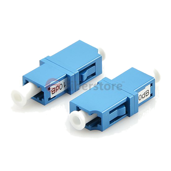
Variable optical attenuators are normally used for testing and measurement. Also they could be used in EDFAs (erbium doped fiber amplifier) for equalizing the light power among separate channels. Fixed optical attenuators have fixed values specified in decibels. The attenuation is expressed in dB and its value cannot be varied. It is ideal for attenuating single-mode fiber connectors in various applications.
Optical attenuators is a critical component of any fiber optic network. Using an attenuator, the transmission signal into the dynamic range of the receiver could be adjusted. This increases the life span of the optical equipment and ultimately provides a clearer transmission signal. Moreover, the utilization of optical attenuators could assure the linear behaviour of optical fiber receivers avoiding optical power overloading. At the same time, it is able to balance the optical power into passive optical network branches and can make measurements on an optical telecommunication system.
Optical attenuators usually work by absorbing the light, like sunglasses absorb the extra light energy. Typically, they have a working wavelength range in which they absorb the light energy equally. However, they should not reflect the light since that could cause unwanted back reflection in the fiber system. Another type of attenuator utilizes a length of high-loss optical fiber, that operates upon its input optical signal power level in such a way that its output signal power level is less than the input level.
Optical attenuators are commonly used in fiber optic communications. They could be used to test power level margins by temporarily adding a calibrated amount of signal loss, or installed permanently to properly match transmitter and receiver levels.
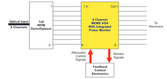
One of the important applications of optical attenuators is channel balancing in WDMs (wavelength division multiplexing). As illustrated in the following picture, an eight channel wavelength multiplexed signal from a trunk line is demultiplexed into individual signals. The signals are of different intensities, and need to be balanced to avoid saturating any of the receivers. So each channel is sent through a corresponding port on an eight channel MEMS (micro-electro-mechanical systems) VOA (variable optical attenuator). The signal strength through the optical attenuator outputs is monitored by a control circuit. If the output signal gets too high or too low, the corresponding optical attenuator is adjusted to bring the light level to the correct range.
As stated above, an optical attenuator is used to reduce the power level when there is too much light deliver through a fiber optic receiver. It is used to adjust optical signal levels thereby increasing network flexibility and providing management of optical power. If you are looking for an optical attenuator, Fiberstore is a primary option. It has many different fixed optical attenuators and variable optical attenuators including fixed LC/APC fiber optic attenuator, fixed SC/UPC fiber optic attenuator, BVA610 optical variable attenuator(0-60dB), etc. For more information, you can visit www.fs.com.