Pre-Terminated Cabling System—An Ideal Solution for Data Centers

When designing and implementing their high-density networks, most data center managers and operators are inclined to options which are more sustainable and environmentally sound. They always expect systems to provide high performance and reliability for maximum network uptime over the long term. Since the demand for higher bandwidth and flexibility for future growth never ending, network administrators now are seeking to the network’s physical media infrastructure to achieve these goals. And the growing adoption of pre-terminated cabling system serves as one of the trend, that is what we will explain in this article.

What Is Pre-Terminated Cabling?

Then what the pre-terminated cabling system refers to and how it differs from field terminated one? In fact, pre-terminated cables go through the same procedures as field terminated cables, but these steps are taken at the manufacturer’s facility or cable assembly house and delivered to the job site with the connectors already terminated, properly polished, and the entire cable assembly tested on either both or one end. Which helps to eliminate the necessity for on-site field termination. Compared with field terminated cabling products, pre-terminated fiber cable assemblies are more convenient and flexible. They are most suited for network installations that are planned well in advance, taking into account both current and future requirements.

What Pre-Terminated Cabling System Can Achieve?

Installing and connecting your cable infrastructure in the data center consists of various labor intensive tasks. And manual field terminations, troubleshooting, and error corrections also extended deployment times, higher installation costs and increased downtime. However, with the deployment of pre-terminated cabling system, you are supposed to benefit from it with the following aspects:

  • Installation time and costs are substantially reduced.
  • Material reductions of 50 percent or more are typical when using pre-terminated systems rather than traditional systems.
  • Network performance and reliability are assured due to in-factory testing and validation of components.
  • Modular components at the physical layer are reusable. They can be disassembled and repurposed to accommodate moves, adds and changes, which provides greater flexibility and portability, as well as a clear migration path to support new technologies and applications as an organization grows and requirements change and evolve.
  • Pre-terminated installations are more precisely planned, which results in a neater, cleaner appearance, as well as faster and easier cable management, maintenance and troubleshooting.
Common Pre-Terminated Fiber Cables

It is undeniable that pre-terminated fiber cabling system indeed offers a constructive and ideal solution to data center management and maintenance. Here in this part, we will further introduce some most commonly employed pre-terminated fiber cables, including fiber patch cables, fiber optic pigtails and MTP/MPO pre-terminated cables.

Fiber Patch Cables

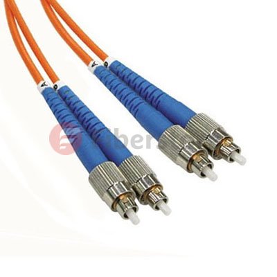
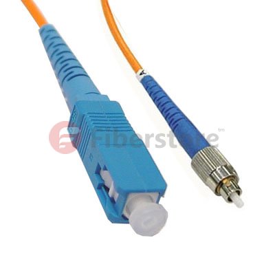
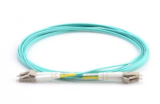
As one of the most used components in fiber optic networks, fiber patch cables help to ensure a reliable temporary fiber optic interconnection. There exists a wide range of fiber patch cables on the market, available in single-mode and multimode versions with PVC, LSZH, OFNP or armored jacket. And connection type options involve LC, FC, SC, ST, MU, MTRJ and E2000 pre-terminated in duplex or simplex fiber. Fiber patch cables are suitable for all kinds of fiber optic connectivity applications.

fiber patch cable

Fiber Optic Pigtails

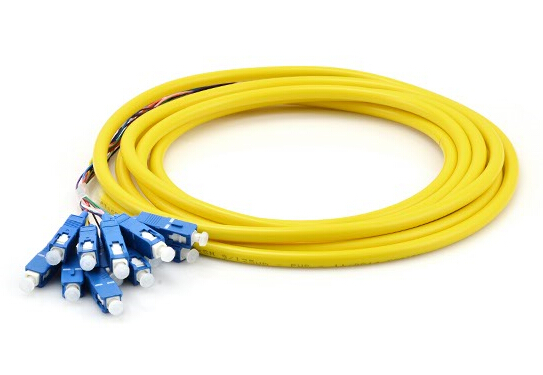
Fiber optic pigtail, which is a fiber optic cable of a specified length, has only one end terminated with the appropriate connector style and an open unterminated end. A pigtail can be fusion spliced onto a pre-terminated fiber optic cable assembly to extend the cable distance or onto field-terminated cables to provide the connectorized end. Pigtails do not need the same configuration or connector style as the opposite end. Keep in mind that when installing pigtails, you must be trained and will need additional equipment, such as a fusion splicer and fusion splice trays.

fiber optic pigtail

MTP/MPO Pre-Terminated Cables

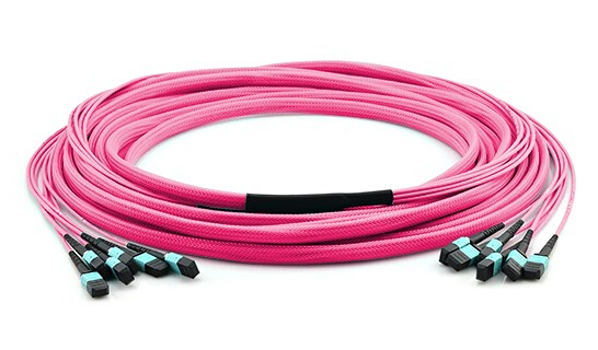
Pre-terminated with high-quality and low loss MTP/MPO connectors, this kind of cable can meet the high-speed, high-density, and wide bandwidth demands of the current and future network. Basically, both MTP/MPO trunk cables and MTP/MPO harness cables are classified into this category. They are available in any fiber mode (single-mode and multimode) and a full range of length options.

MTP/MPO trunk cable

Conclusion

Pre-termination cabling is not just a popular trend, it is an increasingly popular way of delivering a project in a more timely and cost effective manner. Which on the whole can provide benefits for all sizes of project.

The Introduction Of Bend Insensitive Multimode Fiber

Multimode optical fiber transmission performance is mainly limited by the phenomenon of DMD multimode fiber. Multimode optical fiber in the transmission during the pulse, an optical pulse broadening will diverge when such severe divergence condition to a certain extent, between the front pulse is superimposed on each other, so that the receiver can not accurately distinguish each of the optical fiber pulse signal, this phenomenon we called DMD (Differential Mode Delay).There are two main reason, first, the core refractive index distribution is not perfect. Multimode fiber cables DMD is the combined effect of the dispersion characteristic of the propagation time between the different radial positions of the incident pulse and the optical mode, the index multimode fiber refractive index profile can be designed well DMD characteristics. But DMD of refractive index profile is very sensitive to small deviations, and therefore it must be very precisely controlled in multimode fiber production, to achieve the perfect design values of the refractive index profile distribution. Second, the fiber central depression. A central depression is the refractive index of the fiber core center of decreased phenomenon. This recesses is connection with optical fiber manufacturing process. This will affect the transmission characteristics of the central depression of the fiber, the fiber properties decrease.

Therefore, precise control of the refractive index profile of the fiber and the elimination of the central depression is 10Gb / s Ethernet multimode fiber (OM3 fiber) R & D and production of the main tasks. MCVD and PCVD process is more suitable for the production of OM3 fiber preform. PCVD is the preferred method of manufacturing a multi-mode optical fiber having a number of layers deposited, precise control of the cross-sectional characteristics, the deposition process thousands layer can effectively control the doping amount of the deposited layer to obtain a refractive index distribution required to comply with the theoretical. While the process of collapsing, the recess etching amount by controlling the appearance of pore size can be avoided and the central hub.

10Gb / s Ethernet standard IEEE802.3ae get through, it will a 10Gb / s Ethernet market presented. Development in line with standard Gigabit Ethernet communication products is imperative. Long Fei, Draka, Corning, OFS have been successfully developed in line with TIA/EIA-4Array2AAAC standard 50/125mm laser optimized multimode graded-index optical fiber distribution products. Full bandwidth and DMD injection test results show that the 850nm wavelength, the optical fiber can support the transmission distance of 300 meters above the 10Gigabit network system. Meanwhile, the fiber also supports 10Gigabit Fibre Channel abd 10Gigabit of the OIF (Optical Internetworking Forum) standards, and is compatible with low-rate LED light transmission network.

With the rapid development of FTTx, a large multi-mode optical fiber into the interior, in the indoor environment and the narrow wiring, fiber is subjected to high bending stresses, especially in applications where long fibers are usually more compact wound storage box, it will be under a lot of fiber bending stress. With this, the attenuation properties and mechanical resistance to bending the cable put forward higher requirements. To solve these problems, bend-insensitive multimode fibers into being, similar bend insensitive singlemode fiber (G.657), it becomes a major field of research focus on multi-mode fiber.

In recent years, Draka, Corning, OFS has released OM3/OM4 bend-insensitive multimode fiber products. The fiber is compatible with the current conventional OM3/OM4 multimode fiber and optical fiber refractive index profile by optimizing the design, greatly reduces the fiber macrobend additional attenuation, minimum bend radius is generally up to 7.5mm. OM3/OM4 uses bend insensitive multimode fiber patch cables in a way interior simplifies installation, reducing installation costs and reduce the risk of system interruption or failure. Since the bend-insensitive OM3 / OM4 multimode fiber has many advantages, once launched, it was favored on the market of all ages.

As we know, whether single-mode or multi-mode optical fiber, the numerical aperture (NA) is larger, the better its anti-bending performance. This is because the numerical aperture (NA) is greater, the difference by which the core and cladding refractive index is greater, the stronger the fiber waveguide ability. In a multimode fiber, the refractive index difference between the core of the fiber 62.5μm is twice the fiber core 50μm, and therefore the latter bending performance is poor, because the basic pattern of the fiber core 50μm Design is fixed, unable to improve its performance by increasing its resistance to bending refractive index difference. In the design of the fiber, due to lower Young’s modulus of the inner layer of the coating material, the outer layer of the coating material to increase the Young’s modulus is effective in improving the bending resistance properties. Furthermore, due to lower glass transition temperature Tg of the inner layer of coating material can be improved fiber bending properties at low temperatures. However, in order to more effectively improve the core 50μm anti-bending performance multimode fiber, the fiber must find a way out design from a structure (refractive index profile) .

Bend-insensitive multimode fibers OM3/OM4 structure is similar to the standard multimode fiber, bend-insensitive multimode fibers (bend insensitive multimode fiber, BIMMF) the refractive index profile shown in Figure 12. Wherein the green line is a conventional 50μm multimode graded index profile of the optical fiber, blue and red dotted line for bend-insensitive optical fiber in two designs, the three-section of a multimode optical fiber shown in Figure 13. BIMMF distribution index profile, and the same in the core region 50μm conventional multimode fiber, only the ring groove is provided in the region depressed refractive-index cladding region near the core (called trench-assisted multimode fiber ). In conventional multimode fiber, when the fiber bend radius is too small, light intensity conduction mode will escape the core, causing signal distortion. In the bend-insensitive multimode fiber, the refractive index of the ring groove type subsidence area will form an obstacle to escape the intensity wakefield core barriers, thus effectively reduce the fiber macro bending loss.

Figure 12 50μm multimode fiber refractive index profile

Multimode OM3 Fiber

Figure 13 Conventional 50μm multimode fiber bend insensitive MMF, and two cross-sectional view BIMMF

OM4 Multimode Fiber

The Multimode Fiber Proucts on market

FC-FC Duplex OM1

FC-FC Duplex  62.5/125 OM1 Multimode Fiber Patch Cable

FC-SC Simplex OM2

FC-SC Simplex 50/125  OM2 Multimode Fiber Patch Cable

BIMMF bend-insensitive fiber mode field shown in Figure 14: In the conventional multimode fiber MMF, the guided mode in strong low conductivity state, and in close proximity to the core – cladding interface propagating order modes, because the effective refractive index neff close to the refractive index of the cladding n2, it is weakly conducting state (when the guided mode is equal to the effective refractive index neff cladding refractive index n2, the mode cutoff). Conduction state is weak order modes in the fiber bend radius is too small, its intensity will escape the core, causing signal distortion. In the bend-insensitive fiber BIMMF ring depressed trench type refractive index distribution has two light guide interface, the refractive index in the descending interface, the interface to form a light guide. Because of this interface, enhanced guided mode fiber core conductivity, so that the original order modes weak to lead the state into a strong lead state, shown in Figure 14. In addition, the external interface subsidence ring groove type refractive index distribution of the refractive index of small to large, the formation of refractive interface. Since the refractive index profile of this special structure, there is a leakage conductivity mode (leaky mode) in BIMMF fiber. Leakage mode is the solution of the equation in the intrinsic region outside the cutoff, leaky guided mode parsing mode is outside the cutoff continuous, their field is the same, but its intrinsic value, or the propagation constants are complex solutions Eigenequation, thus There are inherently leaky mode attenuation can not normally spread dissemination. The effective refractive index neff leakage mode of the cladding is less than n2. In the conventional multi-mode fiber, a leaky mode consumption decline rapidly, since the refractive index of a conventional optical fiber structure can not support its propagation in the fiber. And it BIMMF fiber, the refractive index in the form of this particular cross-sectional structure, a strong core to maintain close – cladding interface order modes propagating conductivity, thus effectively improve the flexural properties of the fiber.