Optical Power Meter Tutorial

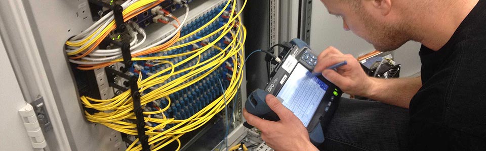
Fiber optic testing in optical communication is an extremely important procedure. Whether installing new cable or testing existing cable, fiber optic testers such as vision fault location, OTDR and optical power meter, are the necessary part that cannot be ignored. This tutorial mainly focuses on the introduction of optical power meter.

Basics of Optical Power Meter

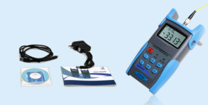
Optical power meter is a common testing instrument. It is often used to accurately measure the power of fiber optic equipment or the power of an optical signal passed through a fiber cable. Sometimes technicians may also use it to measure the power loss of signals. An optical power meter is made up of a calibrated sensor that measures amplifier circuit and a display. The display can show the measured optical power and the corresponding wavelength of the optical signal. The following figure is an example of FSOPM02 handheld optical power meter.

optical-power-meter

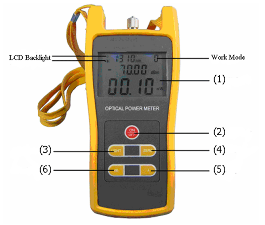
Here is a simple function explanation of the optical power meter.
(1) LCD: display the measurement tested, the selected wavelength, the current operation situation and so on
(2) ON/OFF Key: control turning on or off
(3) dB Key: choose the display unit
(4) ZERO Key: press this key for 3s then enter into zero calibration procedure
(5) “λ” Key: choose different wavelengths
(6) LIGHT Key: turn on or off LCD backlight

Steps of Fiber Optic Loss Measurement with Optical Power Meter

Before using an optical power meter, we should do several preparations. First, getting familiar with the function of each button. And it’s better to do some practice tests before going to do testing works. Second, make clear that how and where your fiber cables are installed in case of unnecessary problems. Last but not least, remember to take notes of your testing results. Besides, it’s important to follow safety notes while doing testing with an optical power. After you have done all the preparing works, it’s time to start the testing tasks. Here are the steps.

  • Turn on the optical power meter and press the λ key to choose the wavelength to be tested.
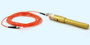
  • Turn on the emitting source and select the tested wavelength, waiting for a while until it becomes stable.
  • Connect the light source (emitting source) to the optical power meter using the fiber cable that is as same as the fiber under test.
  • The optical power meter gets the power measurement value. This value should get close to the tested one.
  • Press the dB key, the reading figure will be shown on the screen. The tested power value will be set to the reference one.
  • Do not cut down the connection between the emitting source and the light source. Then connecting them to the optical fiber link respectively. The reading in dB unit shown on the screen is the tested optical fiber link loss.

Notes: all the connectors and fiber ends should be cleaned with alcohol to ensure an accurate testing result.

Tips for Maintenance

Most fiber optic testers are the instruments providing precise functions for technicians. Therefore they need to be used and maintained properly. Here are some tips for optical power meter maintenance, which should be paid attention to.

  • All the connectors and surfaces should be free from oil, dirt or other contamination to avoid damage and to ensure an accurate result.
  • Dust proof cap should be used to avoid scratch or contamination when optical power meter is not in operation.
  • The light interface is very sensitive, so the connectors should be carefully plugged in and out.
  • If the optical power meter does not need to be used for a long time, it’s better to take out the battery.
Summary

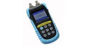
In a word, optical power meter can be used for both optical power measurements and relative loss measurements. Using it properly can help evaluate the quality of fiber optic links transmission. And now on the market, there are different types of optical power meter such as standard type and multifunctional type. Different types have different features. Selecting a suitable one is helpful for a right and reliable cable connection.

Things You Should Know Before Choosing an OTDR

OTDR that is short for optical time domain reflectometry, is a fiber optic tester for the characterization of optical networks that support telecommunications. It can be used to measure loss, optical return loss (ORL) and optical distance on a fiber optic link. Besides, by providing pictorial trace signatures of the fibers under test, an OTDR can offer a graphical representation of the entire fiber optic link. However, there are so many OTDR brands in the market. Choosing the right OTDR for your application can be challenging. So this post is intended for giving some reminders when choosing an OTDR. Hope it may help you.

otdr-application

Why You Need an OTDR?

As we all know, fiber testing is an essential procedure to make sure that the network is optimized to deliver reliable and robust services without fault. So here are two reasons for why an OTDR is needed.

First, service providers and network operators want to insure that their investments into fiber networks are protected. Installers need to use OTDR performing bi-directional tests and providing accurate cable documentation to certify their work. Of course, OTDRs can be used for troubleshooting problems such as break locations due to dig-ups.

Second, premises fiber networks have tight loss budgets and less room for error. Therefore installers have to test the overall loss budget with a light source and power meter, which is a big task. While OTDR can easily pinpoint the causes for excess loss and verify that splices and connections are within appropriate tolerances, which saves lots of time. Besides, it is also the only way to know the exact location of a fault or a break.

What and Where Will You Test?

Before choosing a suitable OTDR, ask yourself the following two questions.

Loss, reflectance, splicing alignment and distance, which one are you going to test? Make sure the OTDR you choose can do what you want easily, quickly and accurately. If you need to make “live” test (like during a “hot cut”—splicing of fibers in a working cable), you need an OTDR that can do an active splice loss measurement in “real time”.

Where are you going to do testing? A good understanding of the applications of an OTDR will help you make the right choice for specific needs. For example, what kind of networks will you test? LAN (local area network), metro or long haul? What is the maximum distance you might have to test? 700 m, 25 km, 150 km?

What Should Be Focused on When Choosing an OTDR?

Many people may be familiar with OTDR but not know how to choose a real right one. Except for the quality that we must focus on, the following three factors also should be attached great importance to.

A Simplified and Task-focused User Interface

Maintaining fiber health is just as challenging and makes fast troubleshooting critical. Almost every OTDR on the market today is designed to cover carrier applications. As a result, many OTDR have very complex user interfaces which require the user to make sense numerous buttons and controls and navigate cumbersome multi-level menus. It’s bad for users improving operating efficiency. So a simplified and task-focused user interface test equipment is important.

simplied-interface

Precision Fiber Channel Information

With the wide use of short patch fibers and various types of fiber connectors, details on network link—loss, connector and reflectance—are critical to ensuring performance. However, OTDR with an attenuation dead zone of more than 3m are no longer applicable for testing data center fiber. But when problems arise, an OTDR with precision fiber channel information can help users with various skill levels efficiently perform troubleshooting and accelerate network recovery.

otdr-wavelengths

Effective Planning and Documentation

As data centers grow and change, it’s challenging to ensure all fibers are installed with certificated quality. Therefore, integrated project management capabilities with cable-by-cable granularity can save time and planning effort. An OTDR with built-in project management capability that allows users plan day-to-day activities without using a personal computer or laptop.

Summary

Selecting a proper OTDR to test your network not only can strengthen its reliability, but also improve the efficiency of the testing job as well as documenting the quality of work. Therefore, before selecting an OTDR, considering the applications and specific needs of your testing work will ensure that it is suited for your applications. FS.COM provides various types of OTDR with different wavelengths such as 850 nm, 1310 nm, 1550 nm and 1625 nm. You can find one that best suits for your network.

Fiber Optic Tester–An Important Tool for Your Network Installation

Fiber optic testing is necessary in optical installations. Accurate testing result can’t be got without high quality fiber optic testers. And there are various kinds of fiber testers available in the market. Today, this article mainly focuses on introducing several common types of fiber optic testers.

fiber-optic-testing

What Should Be tested?

When it comes to fiber optic installation and termination, fiber optic testers cannot be ignored. After the cables are installed and terminated, it’s time for testing. But what should be tested with fiber optic testers? Here are some common parameters which need to be tested.

Power Measurement

Power in a fiber optic system is like voltage in an electrical circuit. It’s important to have moderate power. Because too little power may not distinguish the signal from noise and too much power can cause errors too. So it’s important to measure power.

Loss Testing

Loss testing is the difference value between the power coupled into the cable at the transmitter end and what comes out at the receiver end. In fiber optic system, many things can result in loss such as dirt, connectors and breaks.

Optical Return Loss (ORL)

Optical return loss is the total accumulated light power reflected back to the source from the complete optical span. It includes the back scattering light from the fiber itself and the reflected light from all the joints as well as terminations. Generally, ORL is expressed in decibels (dB). And a high level of ORL will affect the performance of transmission systems.

In addition, some optical testers also can be used for troubleshooting.

Common Types of Fiber Optic Tester

Having known what should be tested in fiber optic testing. Now it’s time to know something about fiber optic testers. Generally, the common types of fiber optic test instruments are visual fault locator (VFL), OTDR (Optical Time Domain Reflectometry), optical power meter, optical multimeter, etc. Following is a brief introduction to the usual types of fiber optic tester.

OTDR

OTDR comprising a laser source and an optical detector operates like radar. It generates short pulses of light and then samples the light scattered back by fiber segments and reflected by connections and other events. OTDR is the main piece of test equipment that is used to analyze a fiber optic link. In addition, as it is possible to calibrate the speed of the pulse as it passes down the fiber, the OTDR also can measure time.

otdr

VFL

VFL is an essential tool for testing cable continuity and locating visual faults. As is known to all, when light encounters a break or sharp bend, it scatters, and scattered light can be observed emerging from the cable. By emitting a laser beam of red light, the VFL can quickly illuminate fiber breaks, damaged connectors, detective splices and tight fiber bends. It even can locate the breaks in a short patch cord, which an OTDR cannot detect. Therefore, VFL is a helpful assistant to the dead zone of DTOR. And it also a basic maintenance tool for fiber network, LAN (Local Area Network) and telecommunication network system.

visual-fault-locater

Optical Power Meter

Optical power meter is a device to measure the power of an optical signal. Its function is to display the incident power on the photodiode. When testing the signal, optical power meter is connected to different places. When testing transmitted power, t is connected directly to the optical transmitter’s output, but it will be connected to the fiber system while testing the received power. In a word, optical power meter is a the primary test instrument for fiber optic networks, as measuring optical signal power is a necessary task for any fiber technician.

optical-power-meter

Optical Multimeter

Optical multimeter, also called optical loss test set, is an instrument that measures several optical parameters such as optical power and wavelength. It adopts an optical laser source and an optical power meter into one handheld instrument, which makes it easy to measure the optical loss of optical fiber links, optical components and fiber networks.

optical-multimeter

Conclusion

In summary, choosing a good quality and high performance fiber optic tester not only can avoid unnecessary problems but also can improve your testing efficiency in fiber optic installation. FS.COM offers a wide range of cable testers and tools to meet any of your demand on copper or fiber installation, termination and troubleshooting. Welcome to visit www.fs.com for more information.