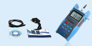
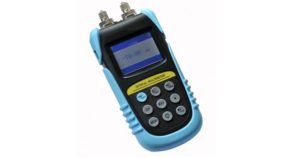
Things You Should Know Before Choosing an OTDR

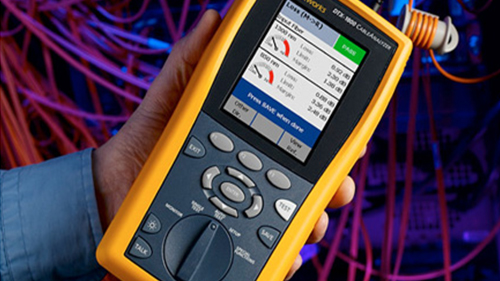
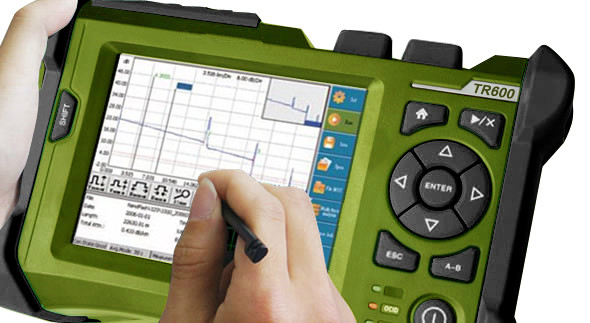
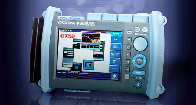
OTDR that is short for optical time domain reflectometry, is a fiber optic tester for the characterization of optical networks that support telecommunications. It can be used to measure loss, optical return loss (ORL) and optical distance on a fiber optic link. Besides, by providing pictorial trace signatures of the fibers under test, an OTDR can offer a graphical representation of the entire fiber optic link. However, there are so many OTDR brands in the market. Choosing the right OTDR for your application can be challenging. So this post is intended for giving some reminders when choosing an OTDR. Hope it may help you.

otdr-application

Why You Need an OTDR?

As we all know, fiber testing is an essential procedure to make sure that the network is optimized to deliver reliable and robust services without fault. So here are two reasons for why an OTDR is needed.

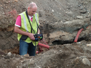
First, service providers and network operators want to insure that their investments into fiber networks are protected. Installers need to use OTDR performing bi-directional tests and providing accurate cable documentation to certify their work. Of course, OTDRs can be used for troubleshooting problems such as break locations due to dig-ups.

Second, premises fiber networks have tight loss budgets and less room for error. Therefore installers have to test the overall loss budget with a light source and power meter, which is a big task. While OTDR can easily pinpoint the causes for excess loss and verify that splices and connections are within appropriate tolerances, which saves lots of time. Besides, it is also the only way to know the exact location of a fault or a break.

What and Where Will You Test?

Before choosing a suitable OTDR, ask yourself the following two questions.

Loss, reflectance, splicing alignment and distance, which one are you going to test? Make sure the OTDR you choose can do what you want easily, quickly and accurately. If you need to make “live” test (like during a “hot cut”—splicing of fibers in a working cable), you need an OTDR that can do an active splice loss measurement in “real time”.

Where are you going to do testing? A good understanding of the applications of an OTDR will help you make the right choice for specific needs. For example, what kind of networks will you test? LAN (local area network), metro or long haul? What is the maximum distance you might have to test? 700 m, 25 km, 150 km?

What Should Be Focused on When Choosing an OTDR?

Many people may be familiar with OTDR but not know how to choose a real right one. Except for the quality that we must focus on, the following three factors also should be attached great importance to.

A Simplified and Task-focused User Interface

Maintaining fiber health is just as challenging and makes fast troubleshooting critical. Almost every OTDR on the market today is designed to cover carrier applications. As a result, many OTDR have very complex user interfaces which require the user to make sense numerous buttons and controls and navigate cumbersome multi-level menus. It’s bad for users improving operating efficiency. So a simplified and task-focused user interface test equipment is important.

simplied-interface

Precision Fiber Channel Information

With the wide use of short patch fibers and various types of fiber connectors, details on network link—loss, connector and reflectance—are critical to ensuring performance. However, OTDR with an attenuation dead zone of more than 3m are no longer applicable for testing data center fiber. But when problems arise, an OTDR with precision fiber channel information can help users with various skill levels efficiently perform troubleshooting and accelerate network recovery.

otdr-wavelengths

Effective Planning and Documentation

As data centers grow and change, it’s challenging to ensure all fibers are installed with certificated quality. Therefore, integrated project management capabilities with cable-by-cable granularity can save time and planning effort. An OTDR with built-in project management capability that allows users plan day-to-day activities without using a personal computer or laptop.

Summary

Selecting a proper OTDR to test your network not only can strengthen its reliability, but also improve the efficiency of the testing job as well as documenting the quality of work. Therefore, before selecting an OTDR, considering the applications and specific needs of your testing work will ensure that it is suited for your applications. FS.COM provides various types of OTDR with different wavelengths such as 850 nm, 1310 nm, 1550 nm and 1625 nm. You can find one that best suits for your network.

Fiber Optic Tester–An Important Tool for Your Network Installation

Fiber optic testing is necessary in optical installations. Accurate testing result can’t be got without high quality fiber optic testers. And there are various kinds of fiber testers available in the market. Today, this article mainly focuses on introducing several common types of fiber optic testers.

fiber-optic-testing

What Should Be tested?

When it comes to fiber optic installation and termination, fiber optic testers cannot be ignored. After the cables are installed and terminated, it’s time for testing. But what should be tested with fiber optic testers? Here are some common parameters which need to be tested.

Power Measurement

Power in a fiber optic system is like voltage in an electrical circuit. It’s important to have moderate power. Because too little power may not distinguish the signal from noise and too much power can cause errors too. So it’s important to measure power.

Loss Testing

Loss testing is the difference value between the power coupled into the cable at the transmitter end and what comes out at the receiver end. In fiber optic system, many things can result in loss such as dirt, connectors and breaks.

Optical Return Loss (ORL)

Optical return loss is the total accumulated light power reflected back to the source from the complete optical span. It includes the back scattering light from the fiber itself and the reflected light from all the joints as well as terminations. Generally, ORL is expressed in decibels (dB). And a high level of ORL will affect the performance of transmission systems.

In addition, some optical testers also can be used for troubleshooting.

Common Types of Fiber Optic Tester

Having known what should be tested in fiber optic testing. Now it’s time to know something about fiber optic testers. Generally, the common types of fiber optic test instruments are visual fault locator (VFL), OTDR (Optical Time Domain Reflectometry), optical power meter, optical multimeter, etc. Following is a brief introduction to the usual types of fiber optic tester.

OTDR

OTDR comprising a laser source and an optical detector operates like radar. It generates short pulses of light and then samples the light scattered back by fiber segments and reflected by connections and other events. OTDR is the main piece of test equipment that is used to analyze a fiber optic link. In addition, as it is possible to calibrate the speed of the pulse as it passes down the fiber, the OTDR also can measure time.

otdr

VFL

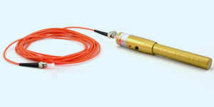
VFL is an essential tool for testing cable continuity and locating visual faults. As is known to all, when light encounters a break or sharp bend, it scatters, and scattered light can be observed emerging from the cable. By emitting a laser beam of red light, the VFL can quickly illuminate fiber breaks, damaged connectors, detective splices and tight fiber bends. It even can locate the breaks in a short patch cord, which an OTDR cannot detect. Therefore, VFL is a helpful assistant to the dead zone of DTOR. And it also a basic maintenance tool for fiber network, LAN (Local Area Network) and telecommunication network system.

visual-fault-locater

Optical Power Meter

Optical power meter is a device to measure the power of an optical signal. Its function is to display the incident power on the photodiode. When testing the signal, optical power meter is connected to different places. When testing transmitted power, t is connected directly to the optical transmitter’s output, but it will be connected to the fiber system while testing the received power. In a word, optical power meter is a the primary test instrument for fiber optic networks, as measuring optical signal power is a necessary task for any fiber technician.

optical-power-meter

Optical Multimeter

Optical multimeter, also called optical loss test set, is an instrument that measures several optical parameters such as optical power and wavelength. It adopts an optical laser source and an optical power meter into one handheld instrument, which makes it easy to measure the optical loss of optical fiber links, optical components and fiber networks.

optical-multimeter

Conclusion

In summary, choosing a good quality and high performance fiber optic tester not only can avoid unnecessary problems but also can improve your testing efficiency in fiber optic installation. FS.COM offers a wide range of cable testers and tools to meet any of your demand on copper or fiber installation, termination and troubleshooting. Welcome to visit www.fs.com for more information.

The Applications and Basic Settings of OTDR

OTDR refers to Optical Time-Domain Reflectometer, a test instrument that analyzes the light loss in an optical fiber and verify inline splices on concatenated fiber optic cables and locate faults. If you use fiber optic cables for network connectivity, you ought to know about the applications and basic setting of OTDR.

Applications:
application of OTDR in life

  • OTDR can be used for return loss measurements, although quoted accuracy is not particularly high. It is very useful for measuring points loss on installed systems where it is used to find faults and measure point losses such as caused by splicing. However, to do this accurately is more complicated and time consuming than is commonly supposed. Since a measurement should be taken from both ends of the system and then averaged.
  • OTDR is useful for testing fiber optic cables. It can verify splice loss, measure length and find faults. It simply shows you where the cables are terminated and confirm the quality of the fibers, connections and splices. What’s more, OTDR trace could be also used for troubleshooting, since it can show where breaks are in fiber when trace is compared to installation documentation.
  • OTDR is also widely used for optical cable maintenance and construction. Because it can evaluate the fiber cable length, measure optical transmission and connection attenuation, as well as detect the faulty location of the fiber links.
  • In addition to fiber characterization, OTDR can also be used for sensing chemicals and gases. Because certain substances cause changes to the light guiding properties of the fiber and those can be observed as changes in the measurement curve.

According to the contents above, we could learn that OTDR is a valuable fiber optic tester in many applications. However, if you use it in an improper way, it can be misleading and can lead to some unnecessary mistakes. So it is necessary to understand some basic settings when using OTDR. Using an OTDR is not very difficult, but it does require familiarity. Here are some tips on how to minimize the chance of making a costly mistake.

Basic Settings:

  • Fiber Type – first you should choose singlemode or multimode.
  • Wavelength – you usually start with 850 nm on multimode fiber and 1310 nm on singlemode, since the shorter wavelength has more backscatter so the trace will be less noisy.
  • Measurement Parameters – the typical parameters to be set are distance range, resolution, and pulse width.
  • Event Threshold – it determines how much loss or change will be tagged as an event.
  • Index of Refraction – it is the speed of light in the fiber. You can obtain this figure from the fiber manufacturer. In most cases, you can take it directly from a standard specific sheet.
  • Display Units – they are usually labeled in feet or meters.
  • Storage Memory – this should be cleared so a new figure can be saved or stored.
  • Dead Zone Jumper – you must connect this fiber which should be sufficiently long between the OTDR and the fiber under test. Sometimes you may also have to connect it at the far end of the cable.

OTDR is valuable test instruments that can illuminate problems in your optical fiber. Once you’re acquainted with what it is used for and learn some basic settings about it, you’ll be prepared to detect and eliminate your optical fiber events. It is an ideal test instrument applied to return loss measurement, fiber optic cables testing, optical cable maintenance and construction, as well as sensing chemicals and gases etc.

How to Troubleshoot a Faulty PON With an OTDR

It is easy to trouble shoot the failure which occurs on a point-to-point FTTx network by using an optical time domain reflectometer (OTDR) test. However, troubleshooting a faulty point-to-multipoint network (i.e., PON network) differs significantly and are more complex than a point to point network. This post will introduce the potential faults which may occur in a PON, and explain how to troubleshoot them with an OTDR.

Brief Introduction of PON
A PON (passive optical network) is a telecommunications network that uses point-to-multipoint fiber to the premises in which unpowered optical splitters are used to enable a single optical fiber to serve multiple premises. A basic PON (see Figure 1) consists of an optical line terminal (OLT) at the service provider’s central office and a number of optical network termination (ONT) or optical network units (ONUs) near end users. Sometimes, a second splitter can be connected in cascade to the first splitter to dispatch services to buildings or residential areas (see Figure 2). The International Telecommunications Union (ITU-T) and Institute of Electrical and Electronic Engineers (IEEE) have created several standards for optical access systems based on PON architecture (G.982, G.983 or G.984 for ITU and 802.3ah or 802.3av for IEEE).

Figure 1. simple PON topology

Figure 1. Simple PON Topology

Figure 2.Cascaded PON topology

Figure 2. Cascaded PON Topology

Due to its architecture, operators can easily determine which subscribers are affected, and can also identify possible fault elements such as how many customers are affected and whether the PON is cascaded by using the network monitoring system at the Network Operation Center (NOC).

Possible Scenarios & Potential Faults of a PON
In general, we divide the faulty case of a PON as three scenarios. One case is that only one customer is affected. And the other case is occured in the cascaded PON and all affected customers are connected to the same splitter. The last case is all customers dependant on the same OLT are affected whether the PON is cascaded or not. In the first case, there are three probable potential faults. Fault may appear in the distribution fiber between the cutsomer and the closest splitter, or in the ONT equipment, or even appear in the customer’s home wiring. See Figure 3 (a) & (b).

Figure 3. PON case1.1

Figure 3 (a). PON Case 1—Possible Faults When Only One Subscriber is Affected

Figure 3. PON case1.2

Figure 3 (b). PON Case 1—Possible Faults When Only One Subscriber is Affected

When all customers connected to the same splitter cannot receive service, but others connected to the same OLT can, namely the second case, the cause may be that there is a fault at the last splitter or in the fiber link between the cascaded splitters. See Figure 4.

Figure 4 PON Case 2

Figure 4. PON Case 2—Cascaded PON with Affected Subscribers Connected to Last Splitter

To the thrid case described above, if all customers are affected, the fault may occur in the splitter closest to the OLT, or in the feeder fiber/cable of the network, or directly in the OLT equipment, as the Figure 5 shown.

Figure 5 PON Case 3

Figure 5. PON Case 3—All Subscribers are Affected (All Connected to the First Splitter)

In addition, we should know that if connectors are available at the splitters, terminals, or drops, isolating part of the faulty network will become easier. Inspecting connectors and taking OTDR measurements using 1310/1550 nm wavelengths are often performed on network sections that are out of service.

Why Use The Specific In-service Portable OTDR Device?
In order to troubleshoot PON networks in service, two dedicated tools are available — PON power meter and In-service 1625 or 1650 nm OTDR. As we know, a PON power meter is normally employed to verify that the signal is transmitted correctly to and from the ONT. A PON meter measures the power levels of all the signals and can then discriminate whether the issue comes from the customer’s ONT or from the network. However, you might be very confused with that why use In-service OTDR. The use of a classical OTDR with 1310 or 1550 nm test wavelengths would interfere with the traffic signals and disturb the traffic. At the same time, the traffic signals could also disturb the receiver of the OTDR, making it difficult to interpret OTDR traces. Due to mutual disturbances, classical OTDRs cannot be used, and specific in-service OTDRs are required.

The in-service OTDR was designed specifically for testing live fiber networks. This dedicated device uses an out-of band wavelength (test wavelength far away from traffic wavelength) to enable OTDR testing without disturbing either the network transmitters or the receivers. In the case of a PON network, WDM is no longer needed, except for monitoring purposes (using a remote fiber test system). The PON network is a point-to-multipoint configuration and the troubleshooting test is performed directly from an accessible element (ONT or splitter). The operator can disconnect the element because service is already off downstream toward the customer. First, the in-service OTDR must not disturb the other customers while shooting the OTDR test wavelength upstream toward the OLT, which is most likely the case, as OLTs reject signals above 1625 nm, based on ITU-T recommendations. Second, the traffic signals that the OTDR receives will be rejected to obtain accurate OTDR traces. The specific long-pass filter used to protect the OTDR diode can be added either via a jumper between the OTDR and the network or built into the OTDR.

Most equipment providers enable the use of the 1625 nm wavelength for safe testing. Some countries, such as Japan, are nevertheless pushing the 1650 nm wavelength as reflected in the ITU-T L.41 recommendation, which provides maintenance wavelengths on fiber-carrying signals. The 1650 nm wavelength is preferred based on the design of the filters and also because it is further away from the traffic signals (current and future PON technologies).

Case of PON Troubleshooting with OTDR
In order to make the whole troubleshooting or testing work smothly, it is essential to select the right OTDR tool, the correct pulse width, and the best location to start troubleshooting. OTDR configuration should be set according to the equipment being qualified and the distance to cover.

In response to the possible scenarios and potential faults of a PON described above, here are some solutions with OTDR to be introduced in the following. To avoid complexity, this document only analyzes the cases where connectors are only available at the ONT/OLTs.

Solution 1: Troubleshooting of the Distribution Fiber
Simple PON—Only one subscriber affected. Consider that no connectors are available at the splitter.(see Figure 6)

Case Test Location OTDR Direction What must be Seen Comment Pulse Width to be use Specific OTDR
Case 1 one customer down Customer’s home Disconnect the ONT Upstream Distribution fiber up to the closest splitter Testing through the splitter is not required, as the issue is only on the disrtibution fiber side. Short pluse 3 to 30 ns In-service OTDR

Figure 6-solution1

Figure 4. OTDR is Shot Upstream and Trace only Matters up to the Splitter

Solution 2: Troubleshooting of the Distribution Fiber and the Fiber between the Two Splitters in case of a Cascaded Network
All customers linked to the second splitter are down. Let’s consider the case where no connectors are available at the splitter.(See Figure 7.)

Case Test Location OTDR Direction What must be Seen Comment Pulse Width to be use Specific OTDR
Case 2 all the customers are down after the second splitter Customer’s home Disconnect the ONT Upstream Distribution fiber up to the two splitters Testing through the closest splitter is required. Medium pluse 100 to 300 ns In-service OTDR – short dead zone

This case requires viewing the signal after the splitter. The OTDR used must be optimized for this application and have the shortest possible dead zone as the splitter typically provides 7 to 10 dB loss.

Figure 7-solution 2

Figure 5. OTDR is Shot Upstream and Trace should Display the Traffic through the Last Splitter up to the First One

Solution 3: Troubleshooting of the Feeder
Information received at the NOC shows that all customers are down. As the problem likely comes from the feeder side, the most common way to test the faulty network is to shoot an OTDR downstream from the OLT.(See Figure 8.)

Case Test Location OTDR Direction What must be Seen Comment Pulse Width to be use Specific OTDR
Case 3 all customers are down OLT Downstream Feeder Testing through the splitter is unnecessary. Short pluse 3 to 30 ns Unnecessary

Figure 8-solution 3

Figure 6. OTDR is Shot Downstream and Trace should Display the Traffic Down to the First Splitter

Note: OTDR testing directly from the OLT is certainly the preferred choice when a faulty feeder is suspected (Solution 3), but this method is not recommended in the other cases.

Other PON Test Tools
Except the OTDR, there are some test tools used in PON troubleshooting in different phases, such as PON power meter, loss test set, IP testers (voice, data, video) and coaxial testers etc. Fiberstore can offer these test tools for you with high quality and competitive price. Such as ODTR, we can offer a variety of types of ODTRs in different brands, e.g. JDSU, YOKOGAWA. In addition, more PON related products can be found in Fiberstore. For more information, please visit our website or contact us over sales@fiberstore.com.