The Evolution of 10GbE Cabling Technologies

Since Ethernet technology is born in 1970s, it has evolved continuously to meet the never-ceasing demands of even faster rates of data transmission, such as 10 Gigabit Ethernet (GbE). Along with this ongoing evolution, the cabling technologies that support the 10GbE applications have also advanced, so as to provide greater bandwidth to transmit data with reasonable cost and decreased complexity. Maybe you have few insights in this evolution. Don’t worry. This text mainly talks about the evolution of 10GbE cabling technologies, including fiber and copper cabling technologies.

The Institute of Electrical and Electronics Engineers (IEEE) 802.3 working group has published several standards regarding 10GbE, including 802.3ae-2002 (fiber -SR, -LR, -ER), 802.3ak-2004 (CX4 copper twin-ax InfiniBand type cable), etc. Actually, the evolution of cabling technologies have walked in step with that of 10GbE standards, especially associated with the difference between IEEE802.3ae and IEEE802.3ak standards.

IEEE802.3ae

Ratified in June 2002, the IEEE802.3ae standard outlined the following port types.

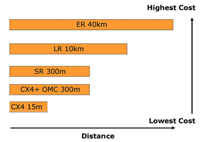
10GBASE-SR—It supports 10GbE transmission over standard multi-mode fiber (MMF) with distances of 33m on OM1 and 86m on OM2. Using 2000 MHz/km MMF (OM3), up to 300-m link lengths are possible. Using 4700 MHz/km MMF (OM4), up to 400 meter link lengths are possible. Like SFP-10G-SR-S (shown below), this Cisco 10GBASE-SR module listed in Fiberstore is able to support up to 300m using OM3 at the maximum data rate of 10.3125Gbps. In addition, SR is the lowest-cost optics (850nm) of all defined 10GbE optics.

SFP-10G-SR-S, supporting 300m link length using OM3

10GBASE-LR—This port type uses higher cost optics (1310nm) than SR and requires more complex alignment of the optics to support 10km link length over single-mode fiber (SMF).

10GBASE-ER—It’s a port type for SMF and uses the most expensive optics (1550nm) lasers, enabling a reach of 40km over engineered links and 30km over standard links.

IEEE802.3ak

Approved in February 2004, this IEEE802.3ak standard only defined 10GBASE-CX4—the first 10GbE copper cabling standard.

10GBASE-CX4—It’s a low-cost 10GbE solution intended for copper cabling with short-distance connectivity. Its affordability and wide availability makes 10GBASE-CX4 ideal for wiring closet and data center connectivity.

The CX4 standard transmits 10GbE over four channels using twin-axial cables which originated from Infiniband connectors and cable. The CX4 standard committee defined that the cables should be tighter in electrical specifications. Therefore, CX4 standard is not appropriate when longer length (>10 Infiniband cable is required. And It’s recommended to use only cables that are designed to meet IEEE 802.3ak specifications.

Another aspect of the CX4 cable is the rigidity and thickness of the cable. The longer the length used, the thicker the cable is. CX4 cables must also be factory-terminated to meet defined specifications.

After comparison between IEEE802.3ae and IEEE802.3ak standards, here goes a picture about the cabling cost and distance considerations.

 cabling cost and distance considerations

Besides IEEE802.3ae and IEEE802.3ak standards, there also exists IEEE802.3an standard. Proposed in November 2002, IEEE802.3an defined 10GBASE-T using unshielded twisted-pair (UTP) style cabling. The goal of this copper standard is to improve the performance and distance of copper cabling at a cost that is lower or similar to fiber.

From the above introduction, the evolution of cabling technologies is associated with the evolution of 10GbE standards. As 10GbE deployment becomes a commonplace, it’s of great importance to make wise cabling strategies.

Conclusion

Spurred by the demand for faster application speeds, cabling technologies evolved to support the 10GbE standards, thus to better accommodate bandwidth-intensive applications and traffic types. With 10GbE technology being pervasive, it’s necessary to understand the the different 10GbE standards and cabling technologies (mentioned above). Fiberstore supplies 10GbE application solutions, transceivers, copper and fiber cables all included, like AFBR-703SDZ-IN2, a 10GBASE-SR SFP+ transceiver. For more information about 10GbE system solutions, you can visit Fiberstore.

Why Choose the Shielded Cabling System

Shielded VS. Unshielded

In Network Cabling system at all levels, there are two main technical types: Shielded and Unshielded cabling systems. Since the earliest fabric cabling standards since its establishment types on these two technologies are widespread in the market. Germany, Australia, Switzerland and France in the first preference or relatively shielded cabling system, while in other parts of the world, the more popular non-shielded cabling system and will soon be adopted. Both shielded and unshielded gigabit transfer rate to meet the requirements, but when the transmission rate up to Gigabit or even higher, the shield system to support the stability of the advantages of the high frequency transmission becomes very apparent.

What is the function of shielded?
F/UTP

F/UTP cable shielding structure is four pairs of wires in the data cable outside the contractor a layer of aluminum foil shielded, this layer of shielding can be reduced to a great extent the total package:

1. This is the root of the signal transmission cable radiated interference signals on the impact of adjacent data cable (for example: the same bundle of cables in the adjacent data cable).

2. Interference from other data cable or other interference source signal for this cable.

3. For a high quality data transmission system, which is significant in two kinds of effects. If the external interference signal is strong enough it will happen with the normal transmission signal stack a plus, resulting in reduced transmission performance even the entire system can not work properly.

S/FTP

S/FTP structure in addition to the total package of braided foil shield, Twisted Pair Cable is respectively in each pair with a layer of aluminum foil shield to protect the transmission signal does not interfere with each other, so near-end crosstalk attenuation (NEXT)performance dramatically.  NEXT better performance means higher SNR and better transmission quality and faster system output. S/FTP shielded cables NEXT excellent structural performance of other cables (such as non-shielded U/UTP) can not be compared, therefore, ISO11801 on the Cat 7 (600MHz) and Cat 7a  (1000MHz) only provides the S/FTP cable structure, U/UTP cannot meet.

10GBase-T make data cable is facing new problems: Alien Crosstalk

2006 Copper Gigabit Ethernet applications published the proposed new standard transport protocols 10GBASE-T compared to 1000Base-T, its transmission rate increased 10 times. 1000BASE-T copper cabling required parameters (Attenuation, NEXT, Return Loss, etc.) the bandwidth required to reach 1-100MHz, with UTP Cat 5e (Class D) cabling system to meet requirements. 10GBASE-T cabling channel requirements of all component parameters have to be up to 500MHz bandwidth, which requires copper to reach at least Cat.6A (Class Ea) or higher level.

Along with the development of 10GBASE-T, external noise problems become more evident, resulting in a specification for external noise to be used to assess in the same bundle of cables, the interaction between different cables. This is what we call Alien Crosstalk. Alien Crosstalk will increase with the increase of frequency. Worse, 10GBASE-T confronted with external noise, will not be able to “adaptive” to lower the rate at which the network may be subsequently face paralysis. Therefore, to support 10GBASE-T cabling system application, the ability to resist alien crosstalk is vital.

  • Since 10GBASE-T high transmission frequencies and complex coding method is very sensitive to the external noise.
  • Shielding system excellent coupling atttenuation performance makes it naturally have to resist alien crosstalk.
  • The unshielded system against alien crosstalk is usually only on the performance of 0dB.
  • Shielding system in the design is completely satisfy the application of 10G.
The installation of 10GBase-T: U/UTP VS. FTP

Unshielded system: As far as possible away from power cable during installation; Different applications (1Gb/s and 10Gb/s) in the same pipeline transmission will cause the external crosstalk.

Shielding system: With the power cable can be reduced separation distance; Allow different applications (1 Gb / s and 10 Gb / s) in the same pipeline transmission; Does not need additional external crosstalk test field.

The separation distance between the data cable and power cable

In EN50174 standard defines the content of different coupling attenuation value level of data cable, respectively, from A (low coupling attenuation, worse) to D (high coupling attenuation, good) four levels.

Installers need to know which cable separated levels to determine the choice of the data requirements of the standard cable with power cable between the minimum separation distance. Data cable coupling attenuation higher the value and power cables minimum separation distance between the smaller.

Relative to the shielded cable, the unshielded (U/UTP) separation distance between cable and power cable to further. In the implementation of the project, if need the data cable and power cable isolation far distance, we need a bigger size pipe/bridge, or even additional bridge, doing this will no doubt have higher cost, sometimes limited to the bridge installation space. To make matters worse, these additional requirements often neglected or ignored, resulting in network system is the key point of interference.

Grounding

For shielded, unshielded systems and Fiber Optics Cable, all need to implement protective grounding. Because of the need to consider personal and equipment safety, therefore no matter adopt what kind of cabling system, the metal part of the system must be grounded.

For the shielding system, also need to implement the functional ground. Grounded shielding system functions with respect to the implementation of non-shielded systems only difference is that when you install the module connector and the cable shielding mask area area connected.

Overview

Shielding system relative to the unshielded system has been greatly improved EMC performance. For Gigabit Ethernet applications, shielding against external interference effects is essential, and shielded cabling system had to meet the standards in the design of anti-alien crosstalk (A-XT) requirements, can effectively prevent the cable from the adjacent between the external crosstalk.