As long as you follow the ANSI/TIA/EIA-568-B Standard, most of your communications infra-structure will be pretty similar and will not vary based on whether it is supporting voice or a specific data application. The horizontal cables will all follow the same structure and rules. However, when you start using the cabling for data applications, you’ll notice some differences. We will now take a look at a couple of possible scenarios for the usage of a structured cabling system.
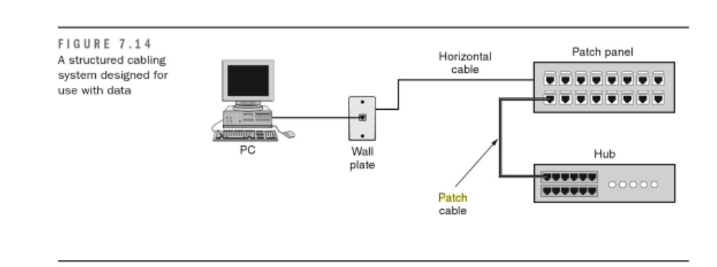
The first scenario, shown in Figure 7.14, shows the typical horizontal cabling terminated to a patch panel. The horizontal cable terminates to the 110-block on the back of the patch panel. When a workstation is connected to the network, it is connected to the network hub by means of a RJ-45 patch cable that connects the appropriate port on the patch panel to a port on the hub.
The use of a generic patch panel in Figure 7.14 allows this cabling system to be the most versatile and expandable. Further, the system can also be used for voice applications if the voice system is also terminated to patch panels.
Another scenario involves the use of 110-blocks with 50-pin Telco connectors. These 50-pin Telco connectors are used to connect to phone systems or to hubs that are equipped with the appropriate 50-pin Telco interface. These are less versatile than patch panels because each connection must be termiated directly to a connection that connects to a hub.
In past years, we have worked with these types of connections, and network administrators have reported to us that these are more difficult to work with. Further, these 50-pin Telco conectors may not be interchangeable with equimpent you purchase in the further. Figure 7.5 shows the use of a 110-block connecting to network equipment using a 50-pin Telco connector.
A final scenario that is a combination of the patch-panel approach and the 110-block approach is the use of a 100-block patch cables (such as the one shown previously in Figure 7.9). This is almost identical to the patch-panel approach, except that the patch cables used in the telecommunications closet have a 110-block connector on one side and an RJ-45 on the other. This configuration is shown in Figure 7.16
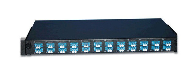
The previous examples are fairly simple and involve only one wiring closet. Any installation that requires more than one telecommunications closet and also one equipment room will require the service of a data backboane. Figure 7.17 shows an example where data backbone cabling is required. Due to distance limitations on horizontal cable when it is handling data applications, all horizonatal cable is terminated to network equimpment (hubs) in the telecommunications closet. The hub is then linked to other hubs via the data backbone cable. Now recommend you two fiber optic patch panels, following picture shows the details.
This 12 port fiber patch panel is designed to fit on a standard 19″ rack and provide optimal protection for your fiber optic applications. There are two cable entry points on the back of the fiber housing fitted with rubber grommets to protect the fiber optic cable from damage. Along with being loaded with 12 SC connections, each fiber enclosure includes one cable routing spool and one 12 fiber splice tray. Also included are zip ties, cable routing clamps, mounting screws, fiber splice sleeves and installation instructions.
The 24 Port Fiber Patch Panel is fundamental to network system operations; whether it be testing, organization, or maintenance, we as users rely on accessible and dependable panels. Let us help you maintain your network with our Fiber Optic Patch Panels. These sliding rack mount panels feature 24 ports and come pre-loaded with 24 SC Duplex multimode adapters. If you have a few patches to make right away, make use of the included fiber management kit, which has some essential goods such as a PG 13.5 cable gland, 1 splice bridge, 8 bunny clips, 24 fiber strands, and 1 warning label for good measure. These rugged steel panels are finished with black powder coating for a clean finish, are 1U (1.75 in.) height for easy installation and access, and come with labels for easy identification during use.
Our fiber optic patch panels feature anywhere from 6 to 576 ports for the ultimate in flexibility and convenience. Plus, they’re available with LC, SC or ST connections – you’ll be able to integrate any component or piece of equipment, old and new. For modular and cabinet applications, Fiberstore carries rack mounted units that easily install in standard 19″ racks, as well as fiber patch panel wall mount units that feature built-in cable management.


