The Anatomy of MPO Trunk Cable Assembly

New cable designs are being developed to address the specific needs of connectorized cable assemblies. There are various industry-standard tests that evaluate the mechanical and environmental performance of cables and another set of standard tests for connectorized assemblies. In many cases, there are choices made in the cable design parameters, which may affect the cable assembly process, without due consideration of the complications that might be added to the assembly processes. Over the past few years, manufacturers have sought to co-develop new cables and the associated cable assemblies, which improve both the performance and processing of the assemblies. Here we report the development of innovative new trunk cables and associated cable assemblies.

Fiber optic cables are designed to meet rigorous standards for cable performance. These requirements include mechanical and environmental testing such as long length tensile testing and temperature cycling. A successful design is judged by how well it meets these requirements. The cable manufacturer then sells the cable to an assembly manufacturer that will furcate and connectorize the fibers from the cable to make a cable assembly.The furcation removes the outer jacket of the cable and prepares the fibers to receive a connector. Additionally, the furcation terminates the cable strength members and must isolate fiber strain in the cable from the connector. The furcation process may include adding a protective furcation leg over the fibers to provide protection between the end of the cable jacket and the connector. The design of the cable has a significant impact on the design and complexity of the furcation. The objective of this effort was to re-design the cable assembly to improve furcation processing and add customer preferred features to the trunk cable assembly.

Traditional high fiber count trunk cable assemblies have been made with fire retardant ribbon cables. These cables have the advantage that the fiber optic ribbons easily mate to the 12-fiber MPO connectors. The MPO connectors are preferred by customers because they allow quick and easy connection of the trunk cables to the MPO/LC breakout modules in a patch panel. However, the rectangular furcation legs have significant preferential bending which may be bothersome during installation. The ribbon trunk cables have several characteristics that may beaggravating during cable assembly and installation. The cables have a ribbon stack contained within a hard plastic buffer tube that is surrounded by tensile yarn and an outer jacket. This design provides a robust cable but makes a fairly stiff cable with a large bend radius,which may be difficult to route during installation. Furthermore, the cable design drives the requirement for a large furcation plug and pulling grip that requires more space for pulling the cable in during installation.

ribbon cable

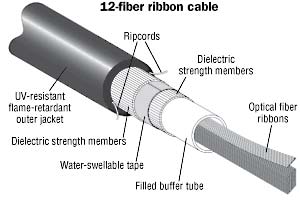
Cables utilized in preterminated assemblies come in many varieties, but there are some common features to all cables. Cables consist of optical fibers, strength members and an outer protective jacket. The cable designs considered in this work were ribbon cables and non-ribbon cables. Each design used 250 µm colored optical fibers. The ribbon cables had the fibers grouped in a linear array with 12 fibers per ribbon. The unitized cables consist of individual units that contain 12 fibers and aramid yarn. One benefit of using ribbon cable is that the installation of multi-fiber connector is simplified because it is not necessary to group the fibers in such an array to install them into the MPO connector. One detriment of the ribbon cable design is that it necessitates rectangular legs to protect the ribbon in the transition from the furcation to the connector. An advantage of unitized cables is that they enable the use of round furcation legs or, with properly designed cable and furcation, the use of the subunits as the legs themselves. Now the following is the introduction of 12-fiber and 24-fiber trunk cable Assemblies.

trunk cable

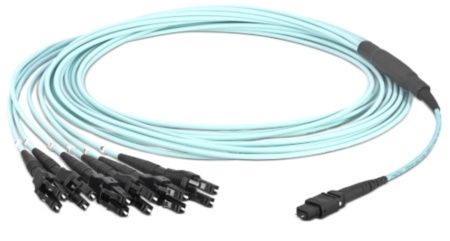
MPO Trunk Assemblies are pre-terminated 12-fiber and 24-fiber cable assemblies. The unique design of the MPO Connector allows for rapid gender and polarity change in the field, in support of standards-compliant cable plant migration from 10G cassette-based systems to 40G MPO connector-based parallel optics cable plant. These trunk cable assemblies optimize cable routing requirements to ensure efficient use of pathway space and significantly reduce installation time and cost. All small diameter trunk cable assemblies are factory terminated and tested to deliver verified optical performance and reliability for improved network integrity. 10Gig versions provide 10 Gb/s network performance up to 300 meters for OM3 and up to 550 meters for OM4 per IEEE 802.3ae 10 GbE standard while maintaining compatibility with legacy systems.

10G fiber backbone or permanent link when mated to MTP Cassettes or fiber adapter panels paired with MPO to LC breakout harnesses. Method A and Method B TIA 568-C compliant for 40G parallel optics multimode applications. Allows system designers to tailor configuration, reach and breakout construction to application requirements; to minimize waste, optimize cable management, speed deployment, improve flexibility and manageability for lower installation costs. Small diameter trunk cable assemblies use 30 – 40% less space which is ideal for high cable density applications.

40GBASE And 100GASE Short Range With MPO Connectors

40GBASE-SR4(short range) is a port type for multimode fiber and uses 850 nm lasers. Its Physical Coding Sublayer 64b/66b PCS is defined in IEEE 802.3 Clause 82 and its Physical Medium Dependent PMD in Clause 86. It uses four lanes of multimode fiber delivering serialized data at a rate of 10.3125 Gbit/s per lane. 40BASE-SR4 has a reach of 100m on OM3 and 150m on OM4. There is a longer range variant 40BASE-eSR4 with a reach of 300m on OM3 and 400m on OM4. This extended reach is equivalent to the reach of 10GBASE-SR.

40GBASE-SR4 operates at 850nm wavelength wavelength using 4×10Gbps paralled transmission over parallel ribbon cable with MPO connectors. Fou multimode fibers, each operating at 10Gbps, are used to transmit 40Gbps in each direction of a duplex link for a total of 8 fibers(4 fibers to transmit in one direction and 4 fibers to transmit from the other direction). These links use ribbon cables or loose tube cable, which are made into a ribbon at the ends of the cable or broken out to an LC(or SC)/MPO breakout cable system. Twelve-five ribbons terminated to a 12-fiber MPO connector are used for each duplex link; however,only 8 fibers out of the 12 are actively used.

The standard supports two multimode fiber types and link distances:100 meters, over OM3 50/125 micron multimode fiber. This fiber, standardized in TIA-492-AAAAC-A, is called 850nm laser-optimized 50/125 micron multimode fiber. The standard aslo supports 150 meters over OM4 50/125 micron multimode fiber. OM4 fiber is standardized in TIA-492-AAAD. These links use QSFP and CFP optical modules.

Most new structured cabling installations use 0M3 and OM4 multimode fiber since it is optimized for use with low-cost 850nm-based optics, and since they are the only multimode types standardized for 40 and 100Gbps Ethernet operations. Low-bandwidth 62.5/125 micron (OM1) and 50/125 micron OM2 multimode fiber do not support 40 and 100Gbps Ethernet operation, and therefore deployments of these fiber types are decreasing over time. Since 40GBASE-SR4 uses low-cost 10GBase-SR like 850nm VCSEL lasers, 40GBASE-SR4 delivers the lowest cost, lowest power, and smallest from-factor optical modules.

Similar to 40 GbE,100 GbE uses electrical lanes of 10Gbps with sc Rambled encoding to create 100Gbps links.100GBASE-CR10 supports links up to 7 meters over 10 pairs of Copper wires in each direction in a jumper cable assembly.100GBASE-SR10 is an optical link that uses Short wavelength lasers with 10 parallel fibers in each direction and supports Short Reach link distances up to 100 meters on OM3 fiber or 150 meters over OM4 fiber on engineered links.

100GBASE-SR10 operates at 850nm wavelength using 10×10Gbps parallel transmission over parallel ribbon cable with MPO connectors. Ten multimode fibers, each operating at 10Gbps, are used to transmit 100Gbps in each direction of a duplex link for a total of 20 fibers(10 fibers to transmit in one direction and 10 fibers to transmit from the other direction). Similar to 40GBASE-SR4, these links use ribbon cables or loose tube cables terminated to 24-fiber MPO connetors;however, only 20 fibers out of the 24 are actively used.

The standard supports two multimode fiber types and like distances:100 meters,over OM3 50/125 micron multimode fiber and 150 meters over OM4 50/125 micron multimode fiber. Low-bandwidth 62.5/125 micron OM1 and 50/125 micron OM2 multimode fiber do not support 40and 100 Gbps Ethernet operation. These links use CXP and CFP optical modules.

Since 100GBASE-SR10 uses low-cost 10GBase-SR like 850nm VCSEL lasers, 100GBASE-SR10 delivers the lowest cost, lowest power, and smallest form-factor optical modules for 100Gbps operation.

The Introduction Of Bend Insensitive Multimode Fiber

Multimode optical fiber transmission performance is mainly limited by the phenomenon of DMD multimode fiber. Multimode optical fiber in the transmission during the pulse, an optical pulse broadening will diverge when such severe divergence condition to a certain extent, between the front pulse is superimposed on each other, so that the receiver can not accurately distinguish each of the optical fiber pulse signal, this phenomenon we called DMD (Differential Mode Delay).There are two main reason, first, the core refractive index distribution is not perfect. Multimode fiber cables DMD is the combined effect of the dispersion characteristic of the propagation time between the different radial positions of the incident pulse and the optical mode, the index multimode fiber refractive index profile can be designed well DMD characteristics. But DMD of refractive index profile is very sensitive to small deviations, and therefore it must be very precisely controlled in multimode fiber production, to achieve the perfect design values of the refractive index profile distribution. Second, the fiber central depression. A central depression is the refractive index of the fiber core center of decreased phenomenon. This recesses is connection with optical fiber manufacturing process. This will affect the transmission characteristics of the central depression of the fiber, the fiber properties decrease.

Therefore, precise control of the refractive index profile of the fiber and the elimination of the central depression is 10Gb / s Ethernet multimode fiber (OM3 fiber) R & D and production of the main tasks. MCVD and PCVD process is more suitable for the production of OM3 fiber preform. PCVD is the preferred method of manufacturing a multi-mode optical fiber having a number of layers deposited, precise control of the cross-sectional characteristics, the deposition process thousands layer can effectively control the doping amount of the deposited layer to obtain a refractive index distribution required to comply with the theoretical. While the process of collapsing, the recess etching amount by controlling the appearance of pore size can be avoided and the central hub.

10Gb / s Ethernet standard IEEE802.3ae get through, it will a 10Gb / s Ethernet market presented. Development in line with standard Gigabit Ethernet communication products is imperative. Long Fei, Draka, Corning, OFS have been successfully developed in line with TIA/EIA-4Array2AAAC standard 50/125mm laser optimized multimode graded-index optical fiber distribution products. Full bandwidth and DMD injection test results show that the 850nm wavelength, the optical fiber can support the transmission distance of 300 meters above the 10Gigabit network system. Meanwhile, the fiber also supports 10Gigabit Fibre Channel abd 10Gigabit of the OIF (Optical Internetworking Forum) standards, and is compatible with low-rate LED light transmission network.

With the rapid development of FTTx, a large multi-mode optical fiber into the interior, in the indoor environment and the narrow wiring, fiber is subjected to high bending stresses, especially in applications where long fibers are usually more compact wound storage box, it will be under a lot of fiber bending stress. With this, the attenuation properties and mechanical resistance to bending the cable put forward higher requirements. To solve these problems, bend-insensitive multimode fibers into being, similar bend insensitive singlemode fiber (G.657), it becomes a major field of research focus on multi-mode fiber.

In recent years, Draka, Corning, OFS has released OM3/OM4 bend-insensitive multimode fiber products. The fiber is compatible with the current conventional OM3/OM4 multimode fiber and optical fiber refractive index profile by optimizing the design, greatly reduces the fiber macrobend additional attenuation, minimum bend radius is generally up to 7.5mm. OM3/OM4 uses bend insensitive multimode fiber patch cables in a way interior simplifies installation, reducing installation costs and reduce the risk of system interruption or failure. Since the bend-insensitive OM3 / OM4 multimode fiber has many advantages, once launched, it was favored on the market of all ages.

As we know, whether single-mode or multi-mode optical fiber, the numerical aperture (NA) is larger, the better its anti-bending performance. This is because the numerical aperture (NA) is greater, the difference by which the core and cladding refractive index is greater, the stronger the fiber waveguide ability. In a multimode fiber, the refractive index difference between the core of the fiber 62.5μm is twice the fiber core 50μm, and therefore the latter bending performance is poor, because the basic pattern of the fiber core 50μm Design is fixed, unable to improve its performance by increasing its resistance to bending refractive index difference. In the design of the fiber, due to lower Young’s modulus of the inner layer of the coating material, the outer layer of the coating material to increase the Young’s modulus is effective in improving the bending resistance properties. Furthermore, due to lower glass transition temperature Tg of the inner layer of coating material can be improved fiber bending properties at low temperatures. However, in order to more effectively improve the core 50μm anti-bending performance multimode fiber, the fiber must find a way out design from a structure (refractive index profile) .

Bend-insensitive multimode fibers OM3/OM4 structure is similar to the standard multimode fiber, bend-insensitive multimode fibers (bend insensitive multimode fiber, BIMMF) the refractive index profile shown in Figure 12. Wherein the green line is a conventional 50μm multimode graded index profile of the optical fiber, blue and red dotted line for bend-insensitive optical fiber in two designs, the three-section of a multimode optical fiber shown in Figure 13. BIMMF distribution index profile, and the same in the core region 50μm conventional multimode fiber, only the ring groove is provided in the region depressed refractive-index cladding region near the core (called trench-assisted multimode fiber ). In conventional multimode fiber, when the fiber bend radius is too small, light intensity conduction mode will escape the core, causing signal distortion. In the bend-insensitive multimode fiber, the refractive index of the ring groove type subsidence area will form an obstacle to escape the intensity wakefield core barriers, thus effectively reduce the fiber macro bending loss.

Figure 12 50μm multimode fiber refractive index profile

Multimode OM3 Fiber

Figure 13 Conventional 50μm multimode fiber bend insensitive MMF, and two cross-sectional view BIMMF

OM4 Multimode Fiber

The Multimode Fiber Proucts on market

FC-FC Duplex OM1

FC-FC Duplex  62.5/125 OM1 Multimode Fiber Patch Cable

FC-SC Simplex OM2

FC-SC Simplex 50/125  OM2 Multimode Fiber Patch Cable

BIMMF bend-insensitive fiber mode field shown in Figure 14: In the conventional multimode fiber MMF, the guided mode in strong low conductivity state, and in close proximity to the core – cladding interface propagating order modes, because the effective refractive index neff close to the refractive index of the cladding n2, it is weakly conducting state (when the guided mode is equal to the effective refractive index neff cladding refractive index n2, the mode cutoff). Conduction state is weak order modes in the fiber bend radius is too small, its intensity will escape the core, causing signal distortion. In the bend-insensitive fiber BIMMF ring depressed trench type refractive index distribution has two light guide interface, the refractive index in the descending interface, the interface to form a light guide. Because of this interface, enhanced guided mode fiber core conductivity, so that the original order modes weak to lead the state into a strong lead state, shown in Figure 14. In addition, the external interface subsidence ring groove type refractive index distribution of the refractive index of small to large, the formation of refractive interface. Since the refractive index profile of this special structure, there is a leakage conductivity mode (leaky mode) in BIMMF fiber. Leakage mode is the solution of the equation in the intrinsic region outside the cutoff, leaky guided mode parsing mode is outside the cutoff continuous, their field is the same, but its intrinsic value, or the propagation constants are complex solutions Eigenequation, thus There are inherently leaky mode attenuation can not normally spread dissemination. The effective refractive index neff leakage mode of the cladding is less than n2. In the conventional multi-mode fiber, a leaky mode consumption decline rapidly, since the refractive index of a conventional optical fiber structure can not support its propagation in the fiber. And it BIMMF fiber, the refractive index in the form of this particular cross-sectional structure, a strong core to maintain close – cladding interface order modes propagating conductivity, thus effectively improve the flexural properties of the fiber.