In the realm of high-speed processing and complex workloads, InfiniBand is pivotal for HPC and hyperscale clouds. This article explores FS’s 100G EDR InfiniBand solution, emphasizing the deployment of QSFP28 EDR transceivers and cables to boost network performance.
What are the InfiniBand HDR 100G Cables and Transceivers
InfiniBand EDR 100G Active AOC Cables
The NVIDIA InfiniBand MFA1A00-E001, an active optical cable based on Class 1 FDA Laser, is designed for InfiniBand 100Gb/s EDR systems. With lengths ranging from 1m to 100m, these cables offer predictable latency, consuming a max of 3.5W, and enhancing airflow in high-speed HPC environments.
InfiniBand EDR 100G Passive Copper Cables
The NVIDIA InfiniBand MCP1600-E001E30 is available in lengths of 0.5m to 3m. With four high-speed copper pairs supporting up to 25Gb/s, it offers efficient short-haul connectivity. Featuring EEPROM on each QSFP28 port, it enhances host system communication, enabling higher port bandwidth, density, and configurability while reducing power demand in data centers.
InfiniBand EDR 100G Optical Modules
The 100Gb EDR optical modules, packaged in QSFP28 form factor with LC duplex or MTP/MPO-12 connectors, are suitable for both EDR InfiniBand and 100G Ethernet. They can be categorized into QSFP28 SR4, QSEP28 PSM4, QSFP28 CWDM4, and QSFP28 LR4 based on transmission distance requirements.
100Gb InfiniBand EDR System Scenario Applications
InfiniBand has gained widespread adoption in data centers and other domains, primarily employing the spine-leaf architecture. In data centers, transceivers and cables play a pivotal role in two key scenarios: Data Center to User and Data Center Interconnects.
Amidst the evolving landscape of 100G InfiniBand EDR, FS’s solution emerges as mature and robust. Offering high bandwidth, low latency, and reduced power consumption, it enables higher port density and configurability at a lower cost. Tailored for large-scale data centers, HPC, and future network expansion, customers can choose products based on application needs, transmission distance, and deployment. FS 100G EDR InfiniBand solution meets the escalating demands of modern computational workloads.
The market’s diverse methods for calculating the optical module-to-GPU ratio lead to discrepancies due to varying network structures. The precise number of optical modules required hinges on critical factors such as network card models, switch models, and the scalable unit count.
Network Card Model
The primary models are ConnectX-6 (200Gb/s, for A100) and ConnectX-7 (400Gb/s, for H100), with the upcoming ConnectX-8 800Gb/s slated for release in 2024.
Switch Model
MQM 9700 switches (64 channels of 400Gb/s) and MQM8700 switches (40 channels of 200Gb/s) are the main types, affecting optical module needs based on transmission rates.
Number of Units (Scalable Unit)
Smaller quantities use a two-tier structure, while larger quantities employ a three-tier structure, as seen in H100 and A100 SuperPODs.
H100 SuperPOD: Each unit consists of 32 nodes (DGX H100servers) and supports a maximum of 4 units to form a cluster, using a two-layer switching architecture.
A100 SuperPOD: Each unit consists of 20 nodes (DGX A100 servers) and supports a maximum of 7 units to form a cluster. If the number of units exceeds 5, a three-layer switching architecture is required.
Optical Module Demand Under Four Network Configurations
Projected shipments of H100 and A100 GPUs in 2023 and 2024 indicate substantial optical module demands, with a significant market expansion forecasted. The following are four application scenarios:
A100+ConnectX6+MQM8700 Three-layer Network: Ratio 1:6, all using 200G optical modules.
A100+ConnectX6+MQM9700 Two-layer Network: 1:0.75 of 800G optical modules + 1:1 of 200G optical modules.
H100+ConnectX7+MQM9700 Two-layer Network: 1:1.5 of 800G optical modules + 1:1 of 400G optical modules.
H100+ConnectX8 (yet to be released)+MQM9700 Three-layer Network: Ratio 1:6, all using 800G optical modules.
For detailed calculations regarding each scenario, you can click on this article to learn more.
Conclusion
As technology progresses, the networking industry anticipates the rise of high-speed solutions like 400G multimode optical modules. FS offers optical modules from 1G to 800G, catering to evolving network demands.
Register for an FS account, select products that suit your needs, and FS will tailor an exclusive solution for you to achieve network upgrades.
As businesses upgrade their data centers, they’re transitioning from traditional 2-layer network architectures to more advanced 3-layer routing frameworks. Protocols like OSPF and BGP are increasingly used to manage connectivity and maintain network reliability. However, certain applications, especially those related to virtualization, HPC, and storage, still rely on 2-layer network connectivity due to their specific requirements.
VXLAN Overlay Network Virtualization
In today’s fast-paced digital environment, applications are evolving to transcend physical hardware and networking constraints. An ideal networking solution offers scalability, seamless migration, and robust reliability within a 2-layer framework. VXLAN tunneling technology has emerged as a key enabler, constructing a virtual 2-layer network on top of the existing 3-layer infrastructure. Control plane protocols like EVPN synchronize network states and tables, fulfilling contemporary business networking requirements.
Network virtualization divides a single physical network into distinct virtual networks, optimizing resource use across data center infrastructure. VXLAN, utilizing standard overlay tunneling encapsulation, extends the control plane using the BGP protocol for better compatibility and flexibility. VXLAN provides a larger namespace for network isolation across the 3-layer network, supporting up to 16 million networks. EVPN disseminates layer 2 MAC and layer 3 IP information, enabling communication between VNIs and supporting both centralized and distributed deployment models.
For enhanced flexibility, this project utilizes a distributed gateway setup, supporting agile execution and deployment processes. Equal-Cost Multipath (ECMP) routing and other methodologies optimize resource utilization and offer protection from single node failures.
RoCE over EVPN-VXLAN
RoCE technology facilitates efficient data transfer between servers, reducing CPU overhead and network latency. Integrating RoCE with EVPN-VXLAN enables high-throughput, low-latency network transmission in high-performance data center environments, enhancing scalability. Network virtualization divides physical resources into virtual networks tailored to distinct business needs, allowing for agile resource management and rapid service deployment.
Simplified network planning, deployment, and operations are essential for managing large-scale networks efficiently. Unnumbered BGP eliminates the need for complex IP address schemes, improving efficiency and reducing operational risks. Real-time fault detection tools like WJH provide deep network insights, enabling quick resolution of network challenges.
Conclusion
Essentially, recent advancements in data center networking focus on simplifying network design, deployment, and management. Deploying technological solutions such as Unnumbered BGP eliminates the need for complex IP address schemes, reducing setup errors and boosting productivity. Tools like WJH enable immediate fault detection, providing valuable network insights and enabling quick resolution of network issues. The evolution of data center infrastructures is moving towards distributed and interconnected multi-data center configurations, requiring faster network connections and improving overall service quality for users.
High-Performance Computing (HPC) has become a crucial tool for solving complex problems and pushing the boundaries of scientific research, and various other applications. However, efficient operation of HPC systems requires specialized infrastructure and support. HPC has emerged as an indispensable tool across various domains, capable of addressing complex challenges and driving innovation in fields such as science, meteorology, finance, and healthcare.
Understanding the importance of data centers in supporting HPC is essential, as knowing the three fundamental components—compute, storage, and networking—that constitute high-performance computing systems is crucial.
Facilities in High-Performance Computing
Intensive computations in HPC environments generate substantial heat, necessitating advanced cooling solutions. Efficient cooling prevents overheating, ensuring system stability and prolonging hardware lifespan. Supporting HPC, data centers employ cutting-edge cooling facilities, including liquid cooling systems and precision air conditioning. Moreover, data center architects explore innovative cooling technologies like immersion cooling, submerging servers in special liquids for effective heat dissipation.
Success in HPC data centers relies on a range of specialized equipment tailored to meet the unique demands of high-performance computing. Key components include data center switches, server network cards, high-speed optical modules, DAC and AOC cables, and power supplies.
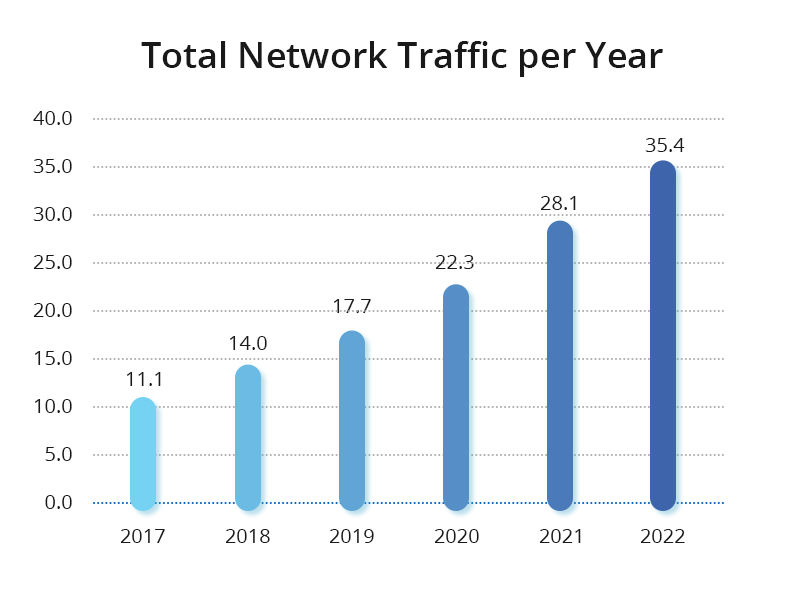
The Growing Demand for Network Infrastructure in High-Performance Computing
With revolutionary technologies like 5G, big data, and the Internet of Things (IoT) permeating various aspects of society, the trajectory towards an intelligent, digitized society over the next two to three decades is inevitable. Data center computing power has become a powerful driving force, shifting focus from resource scale to computational scale.
To meet the ever-growing demand for computing power, high-performance computing (HPC) has become a top priority, especially as computational cluster scales expand from the petascale to the exascale. This shift imposes increasingly higher demands on interconnect network performance, marking a clear trend of deep integration between computation and networking. HPC introduces different network performance requirements in three typical scenarios: loosely coupled computing scenarios, tightly coupled scenarios, and data-intensive computing scenarios.
In summary, high-performance computing (HPC) imposes stringent requirements on network throughput and latency. To meet these demands, the industry widely adopts Remote Direct Memory Access (RDMA) as an alternative to the TCP protocol to reduce latency and maximize CPU utilization on servers. Despite its advantages, the sensitivity of RDMA to network packet loss highlights the importance of lossless networks.
The Evolution of High-Performance Computing Networks
Traditional data center networks have historically adopted a multi-hop symmetric architecture based on Ethernet technology, relying on the TCP/IP protocol stack for transmission. However, despite over 30 years of development, Remote Direct Memory Access (RDMA) technology has gradually replaced TCP/IP, becoming the preferred protocol for HPC networks. Additionally, the choice of RDMA network layer protocols has evolved from expensive lossless networks based on the InfiniBand (IB) protocol to intelligent lossless networks based on Ethernet.
From TCP to RDMA
In traditional data centers, Ethernet technology and the TCP/IP protocol stack have been the norm for building multi-hop symmetric network architectures. However, due to two main limitations—latency issues and CPU utilization—the TCP/IP network is no longer sufficient to meet the demands of high-performance computing. To address these challenges, RDMA functionality has been introduced at the server side. RDMA is a direct memory access technology that enables data transfer directly between computer memories without involving the operating system, thus bypassing time-consuming processor operations. This approach achieves high bandwidth, low latency, and low resource utilization.
From IB to RoCE
RDMA enables direct data read and write between applications and network cards. RDMA’s zero-copy mechanism allows the receiving end to read data directly from the sending end’s memory, significantly reducing CPU burden and improving CPU efficiency. Currently, there are three choices for RDMA network layer protocols: InfiniBand, iWARP (Internet Wide Area RDMA Protocol), and RoCE (RDMA over Converged Ethernet). Although RoCE offers many advantages, its sensitivity to packet loss requires support from lossless Ethernet. This evolution of HPC networks reflects a continuous pursuit of enhanced performance, efficiency, and interoperability.
Enterprise Innovative Solution: Designing High-Performance Data Center Networks
The architecture of data center networks has evolved from the traditional core-aggregation-access model to the modern Spine-Leaf design. This approach fully utilizes network interconnection bandwidth, reduces multi-layer convergence rates, and is easy to scale. When traffic bottlenecks occur, horizontal expansion can be achieved by increasing uplink links and reducing convergence ratios, minimizing the impact on bandwidth expansion. Overlay networks utilize EVPN-VXLAN technology to achieve flexible network deployment and resource allocation.
This solution draws on the design experience of internet data center networks, adopting the Spine-Leaf architecture and EVPN-VXLAN technology to provide a versatile and scalable network infrastructure for upper-layer services. Production and office networks are isolated by domain firewalls and connected to office buildings, labs, and regional center exits. The core switches of the production network provide up to 1.6Tb/s of inter-POD communication bandwidth and 160G of high-speed network egress capacity, with each POD’s internal horizontal network capacity reaching 24Tb, ensuring minimal packet loss. The building wiring is planned based on the Spine-Leaf architecture, with each POD’s switches interconnected using 100G links and deployed in TOR mode. The overall network structure is more streamlined, improving cable deployment and management efficiency.
Future-Oriented Equipment Selection
When envisioning and building data center networks, careful consideration of technological advancements, industry trends, and operational costs over the next five years is crucial. The choice of network switches plays a vital role in the overall design of data center networks. Traditional large-scale network designs often opt for chassis-based equipment to enhance the overall capacity of the network system, but scalability is limited.
Therefore, for the network equipment selection of this project, NVIDIA strongly advocates for adopting a modular switch network architecture. This strategic approach facilitates rapid familiarization by maintenance teams. Additionally, it provides operational flexibility for future network architecture adjustments, equipment reuse, and maintenance replacements.
In response to the ongoing trend of business transformation and the surge in demand for big data, most data center network designs adopt the mature Spine-Leaf architecture, coupled with EVPN-VXLAN technology to achieve efficient network virtualization. This architectural approach ensures convenient high-bandwidth, low-latency network traffic, laying the foundation for scalability and flexibility.
How FS Can Help
FS is a professional provider of communication and high-speed network system solutions for network, data center, and telecommunications customers. Leveraging NVIDIA® InfiniBand switches, 100G/200G/400G/800G InfiniBand transceivers, and NVIDIA® InfiniBand adapters, FS offers customers a comprehensive set of solutions based on InfiniBand and lossless Ethernet (RoCE). These solutions meet diverse application requirements, enabling users to accelerate their businesses and enhance performance. For more information, please visit FS.COM.
With the rapid growth of data centres driven by expansive models, cloud computing, and big data analytics, there is an increasing demand for high-speed data transfer and low-latency communication. In this complex network ecosystem, InfiniBand (IB) technology has become a market leader, playing a vital role in addressing the challenges posed by the training and deployment of expansive models. Constructing high-speed networks within data centres requires essential components such as high-rate network cards, optical modules, switches, and advanced network interconnect technologies.
NVIDIA Quantum™-2 InfiniBand Switch
When selecting switches, NVIDIA’s QM9700 and QM9790 series stand out as the most advanced devices. Built on NVIDIA Quantum-2 architecture, they offer 64 NDR 400Gb/s InfiniBand ports within a standard 1U chassis. This breakthrough translates to an individual switch providing a total bidirectional bandwidth of 51.2 terabits per second (Tb/s), along with an unprecedented handling capacity exceeding 66.5 billion packets per second (BPPS).
The NVIDIA Quantum-2 InfiniBand switches extend beyond their NDR high-speed data transfer capabilities, incorporating extensive throughput, on-chip compute processing, advanced intelligent acceleration features, adaptability, and sturdy construction. These attributes establish them as the quintessential selections for sectors involving high-performance computing (HPC) and expansive cloud-based infrastructures.
Additionally, the integration of NDR switches helps minimise overall cost and complexity, thereby promoting the development of data centre network technology.
The NVIDIA ConnectX®-7 InfiniBand network card (HCA) ASIC delivers a staggering data throughput of 400Gb/s, supporting 16 lanes of PCIe 5.0 or PCIe 4.0 host interface. Utilising advanced SerDes technology with 100Gb/s per lane, the 400Gb/s InfiniBand is achieved through OSFP connectors on both the switch and HCA ports. The OSFP connector on the switch supports two 400Gb/s InfiniBand ports or 200Gb/s InfiniBand ports, while the network card HCA features one 400Gb/s InfiniBand port. The product range includes active and passive copper cables, transceivers, and MPO fibre cables. Notably, despite both using OSFP packaging, there are differences in physical dimensions, with the switch-side OSFP module equipped with heat fins for cooling.
OSFP 800G Optical Transceiver
The OSFP-800G SR8 Module is specifically crafted for utilization in 800Gb/s 2xNDR InfiniBand systems, offering throughput up to 30m over OM3 or 50m over OM4 multimode fibre (MMF) by utilising a wavelength of 850nm through dual MTP/MPO-12 connectors. Its dual-port configuration represents a significant advancement incorporating two internal transceiver engines, fully unlocking the switch’s potential.
This design allows the 32 physical interfaces to support up to 64 400G NDR interfaces. With its high-density and high-bandwidth design, this module enables data centres to seamlessly meet the escalating network demands of applications such as high-performance computing and cloud infrastructure.
Furthermore, the FS OSFP-800G SR8 Module provides outstanding performance and reliability, delivering robust optical interconnection choices for data centres. This module enables data centres to utilise the complete performance potential of the QM9700/9790 series switch, facilitating high-bandwidth and low-latency data transmission.
NDR Optical Connection Solution
Addressing the NDR optical connection challenge, the NDR switch ports utilize OSFP with eight channels per interface, each employing 100Gb/s SerDes. This allows for three mainstream connection speed options: 800G to 800G, 800G to 2X400G, and 800G to 4X200G. Additionally, each channel supports a downgrade from 100Gb/s to 50Gb/s, facilitating interoperability with previous-generation HDR devices.
The 400G NDR series cables and transceivers offer diverse product choices for configuring network switch and adapter systems, focusing on data centre lengths of up to 500 meters to accelerate HPC computing systems. The various connector types, including passive copper cables (DAC), active optical cables (AOC), and optical modules with jumpers, cater to different transmission distances and bandwidth requirements, ensuring low latency and an extremely low bit error rate for high-bandwidth HPC and accelerated computing applications.
In summary, InfiniBand (IB) technology offers unparalleled throughput, intelligent acceleration, and robust performance for HPC, and cloud infrastructures. FS OSFP-800G SR8 Module and NDR Optical Connection Solution further enhance data centre capabilities, enabling high-bandwidth, low-latency connectivity essential for modern computing applications.
Explore the full range of advanced networking solutions at FS.com and revolutionize your data centre network today!
RDMA (Remote Direct Memory Access) enables direct data transfer between devices in a network, and RoCE (RDMA over Converged Ethernet) is a leading implementation of this technology. improves data transmission with high speed and low latency, making it ideal for high-performance computing and cloud environments.
Definition
As a type of RDMA, RoCE is a network protocol defined in the InfiniBand Trade Association (IBTA) standard, allowing RDMA over converged Ethernet network. Shortly, it can be regarded as the application of RDMA technology in hyper-converged data centers, cloud, storage, and virtualized environments. It possesses all the benefits of RDMA technology and the familiarity of Ethernet. If you want to understand RoCE in depth, you can read this article RDMA over Converged Ethernet Guide | FS Community.
Types
Generally, there are two RDMA over Converged Ethernet versions: RoCE v1 and RoCE v2. It depends on the network adapter or card used.
RoCE v1
Retaining the interface, transport layer, and network layer of InfiniBand (IB), the RoCE protocol substitutes the link layer and physical layer of IB with the link layer and network layer of Ethernet. In the link-layer data frame of a RoCE data packet, the Ethertype field value is specified by IEEE as 0x8915, unmistakably identifying it as a RoCE data packet. However, due to the RoCE protocol’s non-adoption of the Ethernet network layer, RoCE data packets lack an IP field. Consequently, routing at the network layer is unfeasible for RoCE data packets, restricting their transmission to routing within a Layer 2 network.
ROCE v2
Introducing substantial enhancements, the RoCE v2 protocol builds upon the RoCE protocol’s foundation. RoCEv2 transforms the InfiniBand (IB) network layer utilized by the RoCE protocol by incorporating the Ethernet network layer and a transport layer employing the UDP protocol. It harnesses the DSCP and ECN fields within the IP datagram of the Ethernet network layer for implementing congestion control. This enables RoCE v2 protocol packets to undergo routing, ensuring superior scalability. As RoCEv2 fully supersedes the original RoCE protocol, references to the RoCE protocol generally denote the RoCE v2 protocol, unless explicitly specified as the first generation of RoCE.
In comparison to InfiniBand, RoCE presents the advantages of increased versatility and relatively lower costs. It not only serves to construct high-performance RDMA networks but also finds utility in traditional Ethernet networks. However, configuring parameters such as Headroom, PFC (Priority-based Flow Control), and ECN (Explicit Congestion Notification) on switches can pose complexity. In extensive deployments, especially those featuring numerous network cards, the overall throughput performance of RoCE networks may exhibit a slight decrease compared to InfiniBand networks.
In actual business scenarios, there are major differences between the two in terms of business performance, scale, operation and maintenance.
Benefits
RDMA over Converged Ethernet ensures low-latency and high-performance data transmission by providing direct memory access through the network interface. This technology minimizes CPU involvement, optimizing bandwidth and scalability as it enables access to remote switch or server memory without consuming CPU cycles. The zero-copy feature facilitates efficient data transfer to and from remote buffers, contributing to improved latency and throughput with RoCE. Notably, RoCE eliminates the need for new equipment or Ethernet infrastructure replacement, leading to substantial cost savings for companies dealing with massive data volumes.
How FS Can Help
In the fast-evolving landscape of HPC data center networks, selecting the right solution is paramount. Drawing on a skilled technical team and vast experience in diverse application scenarios, FS utilizes RoCE to tackle the formidable challenges encountered in High-Performance Computing (HPC). FS offers a range of products, including NVIDIA® InfiniBand Switches, 100G/200G/400G/800G InfiniBand transceivers and NVIDIA® InfiniBand Adapters, establishing itself as a professional provider of communication and high-speed network system solutions for networks, data centers, and telecom clients. Take action now – register for more information and experience our products through a Free Product Trial.
Driven by the booming development of cloud computing and big data, InfiniBand has become a key technology and plays a vital role at the core of the data center. But what exactly is InfiniBand technology? What attributes contribute to its widespread adoption? The following guide will answer your questions.
What is InfiniBand?
InfiniBand is an open industrial standard that defines a high-speed network for interconnecting servers, storage devices, and more. It leverages point-to-point bidirectional links to enable seamless communication between processors located on different servers. It is compatible with various operating systems such as Linux, Windows, and ESXi.
InfiniBand Network Fabric
InfiniBand, built on a channel-based fabric, comprises key components like HCA (Host Channel Adapter), TCA (Target Channel Adapter), InfiniBand links (connecting channels, ranging from cables to fibers, and even on-board links), and InfiniBand switches and routers (integral for networking). Channel adapters, particularly HCA and TCA, are pivotal in forming InfiniBand channels, ensuring security and adherence to Quality of Service (QoS) levels for transmissions.
InfiniBand vs Ethernet
InfiniBand was developed to address data transmission bottlenecks in high-performance computing clusters. The primary differences with Ethernet lie in bandwidth, latency, network reliability, and more.
High Bandwidth and Low Latency
InfiniBand provides higher bandwidth and lower latency, meeting the performance demands of large-scale data transfer and real-time communication applications.
RDMA Support
InfiniBand supports Remote Direct Memory Access (RDMA), enabling direct data transfer between node memories. This reduces CPU overhead and improves transfer efficiency.
Scalability
InfiniBand Fabric allows for easy scalability by connecting a large number of nodes and supporting high-density server layouts. Additional InfiniBand switches and cables can expand network scale and bandwidth capacity.
High Reliability
InfiniBand Fabric incorporates redundant designs and fault isolation mechanisms, enhancing network availability and fault tolerance. Alternate paths maintain network connectivity in case of node or connection failures.
Conclusion
The InfiniBand network has undergone rapid iterations, progressing from SDR 10Gbps, DDR 20Gbps, QDR 40Gbps, FDR56Gbps, EDR 100Gbps, and now to HDR 200Gbps and NDR 400Gbps/800Gbps InfiniBand. For those considering the implementation of InfiniBand products in their high-performance data centers, further details are available from FS.com.
It’s known that training large models is done on clusters of machines with preferably many GPUs per server. This article will introduce the professional terminology and common network architecture of GPU computing.
Exploring Key Components in GPU Computing
PCIe Switch Chip
In the domain of high-performance GPU computing, vital elements such as CPUs, memory modules, NVMe storage, GPUs, and network cards establish fluid connections via the PCIe (Peripheral Component Interconnect Express) bus or specialized PCIe switch chips.
NVLink
NVLink is a wire-based serial multi-lane near-range communications link developed by Nvidia. Unlike PCI Express, a device can consist of muıltiple NVLinks, and devices use mesh networking to communicate instead of a central hub. The protocol was first announced in March 2014 and uses proprietary high-speed signaling interconnect (NVHS).
The technology supports full mesh interconnection between GPUs on the same node. And the development from NVLink 1.0, NVLink 2.0, NVLink 3.0 to NVLink 4.0 has significantly enhanced the two-way bandwidth and improved the performance of GPU computing applications.
NVSwitch
NVSwitch is a switching chip developed by NVIDIA, designed specifically for high-performance computing and artificial intelligence applications. Its primary function is to provide high-speed, low-latency communication between multiple GPUs within the same host.
NVLink Switch
Unlike the NVSwitch, which is integrated into GPU modules within a single host, the NVLink Switch serves as a standalone switch specifically engineered for linking GPUs in a distributed computing environment.
HBM
Several GPU manufacturers have taken innovative ways to address the speed bottleneck by stacking multiple DDR chips to form so-called high-bandwidth memory (HBM) and integrating them with the GPU. This design removes the need for each GPU to traverse the PCIe switch chip when engaging its dedicated memory. As a result, this strategy significantly increases data transfer speeds, potentially achieving significant orders of magnitude improvements.
Bandwidth Unit
In large-scale GPU computing training, performance is directly tied to data transfer speeds, involving pathways such as PCIe, memory, NVLink, HBM, and network bandwidth. Different bandwidth units are used to measure these data rates.
Storage Network Card
The storage network card in GPU architecture connects to the CPU via PCIe, enabling communication with distributed storage systems. It plays a crucial role in efficient data reading and writing for deep learning model training. Additionally, the storage network card handles node management tasks, including SSH (Secure Shell) remote login, system performance monitoring, and collecting related data. These tasks help monitor and maintain the running status of the GPU cluster.
In a full mesh network topology, each node is connected directly to all the other nodes. Usually, 8 GPUs are connected in a full-mesh configuration through six NVSwitch chips, also referred to as NVSwitch fabric.
This fabric optimizes data transfer with a bidirectional bandwidth, providing efficient communication between GPUs and supporting parallel computing tasks. The bandwidth per line depends on the NVLink technology utilized, such as NVLink3, enhancing the overall performance in large-scale GPU clusters.
IDC GPU Fabric
The fabric mainly includes computing network and storage network. The computing network is mainly used to connect GPU nodes and support the collaboration of parallel computing tasks. This involves transferring data between multiple GPUs, sharing calculation results, and coordinating the execution of massively parallel computing tasks. The storage network mainly connects GPU nodes and storage systems to support large-scale data read and write operations. This includes loading data from the storage system into GPU memory and writing calculation results back to the storage system.
New data-intensive applications have led to a dramatic increase in network traffic, raising the demand for higher processing speeds, lower latency, and greater storage capacity. These require higher network bandwidth, up to 400G or higher. Therefore, the 400G market is currently growing rapidly. Many organizations join the ranks of 400G equipment vendors early, and are already reaping the benefits. This article will take you through 400G Ethernet market trend and some global 400G equipment vendors.
The 400G Era
The emergence of new services, such as 4K VR, Internet of Things (IoT), and cloud computing, raises connected devices and internet users. According to an IEEE report, they forecast that “device connections will grow from 18 billion in 2017 to 28.5 billion devices by 2022.” And the number of internet users will soar “from 3.4 billion in 2017 to 4.8 billion in 2022.” Hence, network traffic is exploding. Indeed, the average annual growth rate of network traffic remains at a high level of 26%.
Annual Growth of Network Traffic
Facing the rapid growth of network traffic, 100GE/200GE ports are unable to meet the demand for network connectivity from a large number of customers. Many organizations and enterprises, especially hyperscale data centers and cloud operators, are aggressively adopting next-generation 400G network infrastructure to help address workloads. 400G provides the ideal solution for operators to meet high-capacity network requirements, reduce operational costs, and achieve sustainability goals. Due to the good development prospects of 400G market, many IT infrastructure providers are scrambling to layout and join the 400G market competition, launching a variety of 400G products. Dell’Oro group indicates “the ecosystem of 400G technologies, from silicon to optics, is ramping.” Starting in 2021, large-scale deployments will contribute meaningful market. They forecast that 400G shipments will exceed 15 million ports by 2023, and 400G will be widely deployed in all of the largest core networks in the world. In addition, according to GLOBE NEWSWIRE, the global 400G transceiver market is expected to be at $22.6 billion in 2023. 400G Ethernet is about to be deployed at scale, leading to the arrival of the 400G era.
400G Growth
Companies Offering 400G Networking Equipment
Many top companies seized the good opportunity of the fast-growing 400G market, and launched various 400G equipment. Many well-known IT infrastructure providers, which laid out 400G products early on, have become the key players in the 400G market after years of development, such as Cisco, Arista, Juniper, etc.
400G Equipment Vendors
Cisco
Cisco foresaw the need for the Internet and its infrastructure at a very early stage, and as a result, has put a stake in the ground that no other company has been able to eclipse. Over the years, Cisco has become a top provider of software and solutions and a dominant player in the highly competitive 25/50/100Gb space. Cisco entered the 400G space with its latest networking hardware and optics as announced on October 31, 2018. Its Nexus switches are Cisco’s most important 400G product. Cisco primarily expects to help customers migrate to 400G Ethernet with solutions including Cisco’s ACI (Application Centric Infrastructure), streamlining operations, Cisco Nexus data networking switches, and Cisco Network Assurance Engine (NAE), amongst others. Cisco has seized the market opportunity and is continuing to grow its sales with its 400G products. Cisco reported second-quarter revenue of $12.7 billion, up 6% year over year, demonstrating the good prospects of 400G Ethernet market.
Arista Networks
Arista Networks, founded in 2008, provides software-driven cloud networking solutions for large data center storage and computing environments. Arista is smaller than rival Cisco, but it has made significant gains in market share and product development during the last several years. Arista announced on October 23, 2018, the release of 400G platforms and optics, presenting its entry into the 400G Ethernet market. Nowadays, Arista focuses on its comprehensive 400G platforms that include various series switches and 400G optical modules for large-scale cloud, leaf and spine, routing transformation, and hyperscale IO intensive applications. The launch of Arista’s diverse 400G switches has also resulted in significant sales and market share growth. According to IDC, Arista networks saw a 27.7 percent full year switch ethernet switch revenue rise in 2021. Arista has put legitimate market share pressure on leader Cisco in the tech sector during the past five years.
Juniper Networks
Juniper is a leading provider of networking products. With the arrival of the 400G era, Juniper offers comprehensive 400G routing and switching platforms: packet transport routers, universal routing platforms, universal metro routers, and switches. Recently, it also introduced 400G coherent pluggable optics to further address 400G data communication needs. Juniper believes that 400G will become the new data rate currency for future builds and is fully prepared for the 400G market competition. And now, Juniper has become the key player in the 400G market.
Huawei Technologies
Huawei, a massive Chinese tech company, is gaining momentum in its data center networking business. Huawei is already in the “challenger” category to the above-mentioned industry leaders—getting closer to the line of “leader” area. On OFC 2018, Huawei officially released its 400G optical network solution for commercial use, joining the ranks of 400G product vendors. Hence, it achieves obvious economic growth. Huawei accounted for 28.7% of the global communication equipment market last year, an increase of 7% year on year. As Huawei’s 400G platforms continue to roll out, related sales are expected to rise further. The broad Chinese market will also further strengthen Huawei’s leading position in the global 400G space.
FS
Founded in 2009, FS is a global high-tech company providing high-speed communication network solutions and services to several industries. Through continuous technology upgrades, professional end-to-end supply chain, and brand partnership with top vendors, FS services customers across 200 countries – with the industry’s most comprehensive and innovative solution portfolio. FS is one of the earliest 400G vendors in the world, with a diverse portfolio of 400G products, including 400G switches, optical transceivers, cables, etc. FS thinks 400G Ethernet is an inevitable trend in the current networking market, and has seized this good opportunity to gain a large number of loyal customers in the 400G market. In the future, FS will continue to provide customers with high-quality and reliable 400G products for the migration to 400G Ethernet.
Getting Started with 400G Ethernet
400G is the next generation of cloud infrastructure, driving next-generation data center networks. Many organizations and enterprises are planning to migrate to 400G. The companies mentioned above have provided 400G solutions for several years, making them a good choice for enterprises. There are also lots of other organizations trying to enter the ranks of 400G manufacturers and vendors, driving the growing prosperity of the 400G market. Remember to take into account your business needs and then choose the right 400G product manufacturer and vendor for your investment or purchase.
Data center layout design is a challenging task requiring expertise, time, and effort. However, the data center can accommodate in-house servers and many other IT equipment for years if done properly. When designing such a modest facility for your company or cloud-service providers, doing everything correctly is crucial.
As such, data center designers should develop a thorough data center layout. A data center layout comes in handy during construction as it outlines the best possible placement of physical hardware and other resources in the center.
What Is Included in a Data Center Floor Plan?
The floor plan is an important part of the data center layout. Well-designed floor plan boosts the data centers’ cooling performance, simplifies installation, and reduces energy needs. Unfortunately, most data center floor plans are designed through incremental deployment that doesn’t follow a central plan. A data center floor plan influences the following:
The power density of the data center
The complexity of power and cooling distribution networks
Achievable power density
Electrical power usage of the data center
Below are a few tips to consider when designing a data center floor plan:
Balance Density with Capacity
“The more, the better” isn’t an applicable phrase when designing a data center. You should remember the tradeoff between space and power in data centers and consider your options keenly. If you are thinking of a dense server, ensure that you have enough budget. Note that a dense server requires more power and advanced cooling infrastructure. Designing a good floor plan allows you to figure this out beforehand.
Consider Unique Layouts
There is no specific rule that you should use old floor layouts. Your floor design should be based on specific organizational needs. If your company is growing exponentially, your data center needs will keep changing too. As such, old layouts may not be applicable. Browse through multiple layouts and find one that perfectly suits your facility.
Think About the Future
A data center design should be based on specific organizational needs. Therefore, while you may not need to install or replace some equipment yet, you might have to do so after a few years due to changing facility needs. Simply put, your data center should accommodate company needs several years in the future. This will ease expansion.
Floor Planning Sequence
A floor or system planning sequence outlines the flow of activity that transforms the initial idea into an installation plan. The floor planning sequence involves the following five tasks:
Determining IT Parameters
The floor plan begins with a general idea that prompts the company to change or increase its IT capabilities. From the idea, the data center’s capacity, growth plan, and criticality are then determined. Note that these three factors are characteristics of the IT function component of the data center and not the physical infrastructure supporting it. Since the infrastructure is the ultimate outcome of the planning sequence, these parameters guide the development and dictate the data centers’ physical infrastructure requirements.
Developing System Concept
This step uses the IT parameters as a foundation to formulate the general concept of data center physical infrastructure. The main goal is to develop a reference design that embodies the desired capacity, criticality, and scalability that supports future growth plans. However, with the diverse nature of these parameters, more than a thousand physical infrastructure systems can be drawn. Designers should pick a few “good” designs from this library.
Determining User Requirements
User requirements should include organizational needs that are specific to the project. This phase should collect and evaluate organizational needs to determine if they are valid or need some adjustments to avoid problems and reduce costs. User requirements can include key features, prevailing IT constraints, logistical constraints, target capacity, etc.
Generating Specifications
This step takes user requirements and translates them into detailed data center design. Specifications provide a baseline for rules that should be followed in the last step, creating a detailed design. Specifications can be:
Standard specifications – these don’t vary from one project to another. They include regulatory compliance, workmanship, best practices, safety, etc.
User specifications – define user-specific details of the project.
Generating a Detailed Design
This is the last step of the floor planning sequence that highlights:
A detailed list of the components
Exact floor plan with racks, including power and cooling systems
Clear installation instructions
Project schedule
If the complete specifications are clear enough and robust, a detailed design can be automatically drawn. However, this requires input from professional engineers.
Principles of Equipment Layout
Datacenter infrastructure is the core of the entire IT architecture. Unfortunately, despite this importance, more than 70% of network downtime stems from physical layer problems, particularly cabling. Planning an effective data center infrastructure is crucial to the data center’s performance, scalability, and resiliency.
Nonetheless, keep the following principles in mind when designing equipment layout.
Control Airflow Using Hot-aisle/Cold-aisle Rack Layout
The principle of controlling airflow using a hot-aisle/cold-aisle rack layout is well defined in various documents, including the ASHRAE TC9.9 Mission Critical Facilities. This principle aims to maximize the separation of IT equipment exhaust air and fresh intake air by placing cold aisles where intakes are present and hot aisles where exhaust air is released. This reduces the amount of hot air drawn through the equipment’s air intake. Doing this allows data centers to achieve power densities of up to 100%.
Provide Safe and Convenient Access Ways
Besides being a legal requirement, providing safe and convenient access ways around data center equipment is common sense. The effectiveness of a data center depends on how row layouts can double up as aisles and access ways. Therefore, designers should factor in the impact of column locations. A column can take up three or more rack locations if it falls within the row of racks. This can obstruct the aisle and lead to the complete elimination of the row.
Align Equipment With Floor and Ceiling Tile Systems
Floor and ceiling tiling systems also play a role in air distribution systems. The floor grille should align with racks, especially in data centers with raised floor plans. Misaligning floor grids and racks can compromise airflow significantly.
You should also align the ceiling tile grid to the floor grid. As such, you shouldn’t design or install the floor until the equipment layout has been established.
Plan the Layout in Advance
The first stages of deploying data center equipment heavily determine subsequent stages and final equipment installation. Therefore, it is better to plan the entire data center floor layout beforehand.
How to Plan a Server Rack Installation
Server racks should be designed to allow easy and secure access to IT servers and networking devices. Whether you are installing new server racks or thinking of expanding, consider the following:
Rack Location
When choosing a rack for your data center, you should consider its location in the room. It should also leave enough space in the sides, front, rear, and top for easy access and airflow. As a rule of thumb, a server rack should occupy at least six standard floor tiles. Don’t install server racks and cabinets below or close to air conditioners to protect them from water damage in case of leakage.
Rack Layout
Rack density should be considered when determining the rack layout. More free space within server racks allows for more airflow. As such, you can leave enough vertical space between servers and IT devices to boost cooling. Since hot air rises, place heat-sensitive devices, such as UPS batteries, at the bottom of server racks, heavy devices should also be placed at the bottom.
Cable Layout
Well-planned rack layout is more than a work of art. Similarly, an excellent cable layout should leverage cable labeling and management techniques to ease the identification of power and network cables. Cables should have markings at both ends for easy identification. Avoid marking them in the middle. Your cable management system should also have provisions for future additions or removal.
Conclusion
Designing a data center layout is challenging for both small and established IT facilities. Building or upgrading data centers is often perceived to be intimidating and difficult. However, developing a detailed data center layout can ease everything. Remember that small changes in the plan during installation lead to costly consequences downstream.