Getting to Know About QSFP-40G-UNIV Transceiver

As the switching applications requiring higher bandwidth increased, the need to upgrade from 10G to dense 40 Gigabit Ethernet switching connection also goes on rise. But the optical transceivers widely used at present require to redesign the data center layout if migrating to 40G, for the existing fiber infrastructure cannot satisfy this migration requirement. However, the QSFP-40G-UNIV transceiver can solve this problem perfectly. Why QSFP-40G-UNIV transceiver can resolve the problem successfully? Let’s first to know the basics about it.

Basics of QSFP-40G-UNIV Transceiver

The “UNIV” in item “QSFP-40G-UNIV” means “Universal”. As we all know, common optical transceiver only can operate either on single-mode fiber (SMF) or multimode fiber (MMF), but it can work on both types of fibers. Therefore, QSFP-40G-UNIV transceiver is also called SMF&MMF 40G transceiver or QSFP 40G universal transceiver. This transceiver is a pluggable optical transceiver in an industry standard QSFP+ form factor. It has four channels of 10G multiplexed inside the module to transmit and receive an aggregate 40G signal over a single pair of single-mode or multimode fiber. And it uses a duplex LC connector that makes it work with a wide range of fiber optic cables, including multi-mode OM3 and OM4 and single mode (OS1). Besides, QSFP-40G-UNIV transceiver supports distances up to 150 m over OM3 or OM4 multimode fiber and up to 500 m over single-mode fiber (different vendor may have different specifications).

ariste-qsfp-40g-univ-transceiver-1

Differences and Advantages of QSFP-40G-UNIV Transceiver

There are various types of short reach QSFP transceivers such as QSFP-40G-SR4 and QSFP-40G-XSR4. The longest reach of them on OM3 is 300m. And most of them use MPO-12 connectors and ribbon fiber infrastructure. As a result, if users have to deploy new fiber to upgrade from 10G to 40G or to install MTP/MPO fiber systems, they have to invest more money to change the existing network systems. However, QSFP-40G-UNIV transceiver is different. It has LC connectors and supports several types of cables, allowing for seamless migrations from existing 10 to 40GbE networking without requiring a redesign or expansion of the fiber network.

Here are the advantages of QSFP-40G-UNIV transceiver.

  • Uses existing duplex fiber infrastructure for 40G
  • Identical transceiver for both multi-mode and single-mode fiber for simplified operations and investment protection
  • Support for Digital Optical Monitoring (DOM) and passive network Taps for link quality monitoring and passive data analysis
  • Optically interoperable with IEEE 40GBASE-LR4 and 40G-LRL4 for easy connection to routers and switches in existing networks
  • Supported QSFP+ ports on switches without restrictions
Applications of QSFP-40G-UNIV Transceiver

As have mentioned above, QSFP-40G-UNIV transceiver is a kind of optical transceiver that can be used for both single-mode and multimode fibers. With this unique design, it offers a cost-effective connectivity for data centers’ migration. Here is a simple illustration of the applications using QSFP-40G-UNIV transceivers.

Multimode Direct Connections for Cisco Switches

The following figure shows the simplest and cost-effective way to connect two Cisco Nexus 9396PX switches with Cisco compatible QSFP-40G-UNIV transceivers for multi-mode fiber infrastructure. In this connection, except for the required transceivers, an LC to LC duplex multimode fiber patch cable is also needed to link the two QSFP-40G-UNIV transceivers directly.

ci-qsfp-univ-transceiver

Single-mode 40GbE Interconnection Solution Using QSFP-40G-UNIV Transceivers

With the special characteristic, the use of Cisco compatible QSFP-40G-UNIV transceiver can help network administrators take greatly advantage of reducing deployment and support. The following figure shows a low cost single-mode 40GbE Interconnection solution. These qsfp+ transceivers are connected with LC duplex SMF fiber patch cables. And two fiber enclosures loaded with MTP LGX cassettes and MTP/MPO trunk cables are also needed to realize this connection.

ci-qsfp-univ-transceiver-2

Conclusion

Without having to redesign or change the existing cable infrastructure, qsfp bidi transceivers enable data centers to run at 10G today and to seamlessly upgrade to 40G. It offers a transition path between single-mode and multimode optics with lower cost and more conveniences. FS.COM supplies 40G QSFP transceivers compatible with other major brands including Cisco QSFP-40G-UNIV, Arista QSFP-40G-UNIV, HPE, etc. And those transceivers are 100% tested to provide a satisfying working performance. You can visit FS.COM or contact sales@fs.com for more detailed information.

Overview of BiDi Transceiver Modules

During optical transmission process, it’s no wonder that using one fiber to receive data from networking equipment, and another one to transmit data to the networking equipment. This kind of transmission mode will increase investment cost certainly. Luckily, here is a type of transceiver can solve this problem. It’s bi-directional transceiver. Today, this article will take you to make sense why BiDi transceiver can make it possible to transmit data over one fiber.

Basics of BiDi Transceiver

BiDi is short for bidirectional. BiDi transceiver is a type of fiber optic transceiver which is used WDM (Wavelength Division Multiplexing) bi-directional transmission technology so that it can achieve the transmission of optical channels on a fiber propagating simultaneously in both directions. BiDi transceiver is only with one port which uses an integral bidirectional coupler to transmit and receive signals over a single fiber optical cable. Thus, it must be employed in pairs.

How Does BiDi Transceiver Work?

The obvious difference between BiDi transceivers and traditional two-fiber fiber optic transceivers is that BiDi transceivers are fitted with Wavelength Division Multiplexing (WDM) couplers, also known as diplexers, which combine and separate data transmitted over a single fiber based on the wavelengths of the light. For this reason, BiDi transceivers are also referred to as WDM transceivers.

To work effectively, BiDi transceivers must be deployed in matched pairs, with their diplexers tuned to match the expected wavelength of the transmitter and receiver that they will be transmitting data from or to.

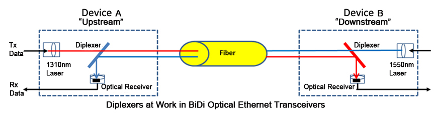
For example, if paired BiDi transceivers are being used to connect Device A (Upstream) and Device B (Downstream), as shown in the figure below, then:

  • Transceiver A’s diplexer must have a receiving wavelength of 1550nm and a transmit wavelength of 1310nm
  • Transceiver B’s diplexer must have a receiving wavelength of 1310nm and a transmit wavelength of 1550nm

bidi transceiver diagram

Common Types of BiDi Transceiver

BiDi SFP Transceiver

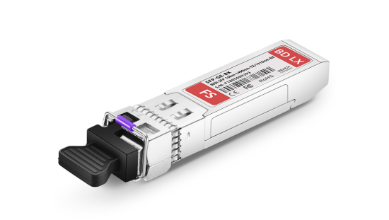
BiDi SFP transceiver is typically applied for the high-performance integrated duplex data link over a single optical fiber. It interfaces a network device mother board (for a switch, router or similar device) to a fiber optic or unshielded twisted pair networking cable. And the most typical wavelength combination is 1310/1490 nm, 1310/1550 nm, 1490/1550 nm and 1510/1570 nm. This BiDi SFP transceiver is used in optical communication for both telecommunication and data bidirectional communications applications.

BiDi SFP+ Transceiver

BiDi SFP+ transceiver is an enhanced SFP transceiver. It is designed for bi-directional 10G serial optical data communications such as IEEE 802.3ae 10GBASE-BX by using 1330/1270nm transmitter and 1270/1330nm receiver. And its transmission distance is up to 20 km.

SFP+ BX

Advantages of BiDi Transceiver

The obvious advantage of utilizing BiDi transceivers, such as BiDi SFP+ and BiDi SFP transceivers, is the reduction in fiber cabling infrastructure costs by reducing the number of fiber patch panel ports, reducing the amount of tray space dedicated to fiber management, and requiring less fiber cable.

While BiDi transceivers (a.k.a. WDM transceivers) cost more to initially purchase than traditional two-fiber transceivers, they utilize half the amount of fiber per unit of distance. For many networks, the cost savings of utilizing less fiber is enough to more than offset the higher purchase price of BiDi transceivers.

Conclusion

In summary, BiDi transceivers can combine and separate data transmitted over a single fiber based on the wavelengths of the light. That is to say, to achieve the same transmitting result, it needs less money. Except for above SFP & SFP+ BiDi transceivers, FS.COM also provides 40G BiDi transceiver. This BiDi transceiver has two 20 Gbps channels, each transmitted and received simultaneously on two wavelengths over a single MMF strand (OM3 or OM4). Any one of the transceivers would meet your different application requirements with high performance.

Related ArticleA Brief Introduction of BiDi SFP Transceiver

Transceiver Module Selection Guide for Your Networking Use

Thanks to the advances made in fiber optical technologies, fiber solutions have been deployed in ever-increasing applications where high-speed and high-performance data transmission is needed. They outweigh the copper solutions in such aspects as higher bandwidth, longer distances and Electromagnetic interference (EMI) immunity. Transceiver module, one of the key components required in such fiber connections for high networking performance, have experienced the never-ceasing industrial designs, from lower port density to higher, from the standard modules to the final hot-pluggable ones, to meet the ever more flexible networking infrastructure.

There is a broad selection of hot-pluggable transceiver modules available for fiber networking use, and you may feel a little confused about how to select the correct transceiver module for your networking transmission. In this article, I will illustrate different aspects of transceivers that need to be known before choosing a transceiver.

Transceiver Module Basics

Before giving guidance to transceiver selection, it’s necessary to know the basics of transceiver. Transceiver is a combination of a transmitter and a receiver in a single package, while they function independently for bidirectional communication. Typically, a fiber optic transceiver converts the incoming optical signal to electrical and the outgoing electrical signal to optical. More specifically, the transmitter takes an electrical input and converts it to an optical output from a laser diode or LED. The light from the transmitter is coupled into the fiber with a connector and is transmitted through the fiber optic cable plant. The light from the end of the fiber is coupled to a receiver where a detector converts the light into an electrical signal which is then conditioned properly for use by the receiving equipment.

Here go the several aspects of transceiver modules that are helpful in your purchasing.

Form-factorseveral MSA transceiver module types

Multi-source agreements (MSAs) between different equipment vendors specify guidelines for electrical and optical interfaces, mechanical dimensions and electro-magnetic specification of a transceiver module. The equipment vendors follow these MSA defined values for designing their systems to ensure interoperability between interface modules. The form-factor or the MSA-type is needed so that the transceiver can mechanically and electrically fit into a given switch, router, etc. Transceiver MSAs define mechanical form factors including electric interface as well as power consumption and cable connector types. There are various MSA types: SFP (eg. MGBSX1), SFP+, XFP, CFP, CFP2, CFP4, QSFP and so on.

Transmission Media

Transceivers can work over single-mode fiber (SMF), multi-mode fiber (MMF), and copper. In different Ethernet applications, media can achieve different link lengths when combined with transceivers. Take Gigabit Ethernet (GbE) applications for example, single mode SFP transceivers can have a transmission distance of 5km to 120km, while multimode SFP transceivers are defined to have the maximum reach of 55om, with copper solution establishing even fewer link length at 25m. Take MGBLX1 for example, this Cisco compatible 1000BASE-LX SFP works through SMF for 10km reach.

Power Budget

The transceiver power budget is the difference between transmitter launch power and receiver sensitivity and has to be 2-3dB larger (Margin) than the measured link loss. If the link loss cannot be measured, it has to be calculated. Therefore transmission distance [km], the number of ODFs, patches and passive optical components (Muxes) have to be known. Common values for power budget are <10, 14, 20, 24, 28, >30dB.

power budget

If you’re seeking high-speed data carrier, transceivers can help accomplish goals. By transmitting data at 10Gbit/s, 40Gbit/s, 100Gbit/s or 12940Gbit/s, they can ensure that data arrives quickly. Transceiver modules that are capable of handling fast speeds can help with downloads and high and low bandwidth video transmission.

Conclusion

Transceiver modules are instrumental in ensuring that the data is transmitted securely, expeditiously, and accurately across the media. Choosing the right type of transceiver for your network is not always easy, but knowing above discussed parameters beforehand helps you narrow it down to a few transceivers. FS.COM offers a sea of transceiver modules which are fully compatible with major brands, like the above mentioned MGBSX1 and MGBLX1, the Cisco compatible transceiver modules.

Considerations About Optical Transceiver Designing

The rapid expansion of fiber optic networks, including data services measured by data volume or bandwidth, shows that fiber optic transmission technology is and will continue to be a significant part of future networking systems. Network designers are becoming increasingly comfortable with fiber solutions, since the use of which allows for more flexible network architecture and other advantages, such as EMI (Electromagnetic Interference) resilience and data security. Optical transceiver plays an really important role in these fiber connections. And while designing fiber optic transceivers, three aspects need to be considered: environmental situation, electrical condition and optical performance.

What Is a Optical Transceiver?

The optical transceiver is a self-contained component that transmits and receives signals. Usually, it is inserted in devices such as routers or network interface cards which provide one or more transceiver module slot. The transmitter takes an electrical input and converts it to an optical output from a laser diode or LED. The light from the transmitter is coupled into the fiber with a connector and is transmitted through the fiber optic cable plant. Then the light from the end of the fiber is coupled to a receiver where a detector converts the light into an electrical signal which is then conditioned properly for use by the receiving equipment. There are a full range of optical transceivers available in telecommunication market, like SFP transceiver, SFP+ transceiver (eg. SFP-10G-SR shown below), 40G QSFP+, 100G CFP, etc.SFP-10G-SR optical transceiver

Optical Transceiver Designing Considerations

It’s true that fiber links can handle higher data rates over longer distances than copper solutions, which drive the even wider use of optical transceivers. While designing fiber optic transceivers, the following aspects should be taken into consideration.

  • Environmental Situation

One challenge comes to the outside weather—especially severe weather at elevated or exposed heights. The components must operate over extreme environmental conditions, over a wider temperature range. The second environmental issue related to the optical transceiver design is the host board environment which contains the system power dissipation and thermal dissipation characteristics.

A major advantage of the fiber optic transceiver is the relatively low electrical power requirements. However, this low power does not exactly mean that the thermal design can be ignored when assembling a host configuration. Sufficient ventilation or airflow should be included to help dissipate thermal energy that is drawn off the module. Part of this requirement is addressed by the standardized SFP cage which is mounted on the host board and also serves as a conduit for thermal energy. Case temperature reported by the Digital Monitor Interface (DMI), when the host operates at its maximum design temperature, is the ultimate test of the effectiveness of the overall system thermal design.

  • Electrical Condition

Essentially, the fiber transceiver is an electrical device. In order to maintain error free performance for the data passing through the module, the power supply to the module must be stable and noise-free. What’s more, the power supply driving the transceiver must be appropriately filtered. The typical filters have been specified in the Multisource Agreements (MSAs) which have guided the original designs for these transceivers. One such design in the SFF-8431 specification is shown below.

filter

  • Optical Performance

Optical performance is measured as Bit Error Rate, or BER. The problem facing designing optical transceiver lie in the case that the optical parameters for the transmitter and receiver have to be controlled, so that any possible degradation of the optical signal while traveling along the fibers will not cause poor BER performance. The primary parameter of relevance is the BER of the complete link. That is, the start of the link is the source of the electrical signals which drive the transmitter, and at the end, the electrical signal is received and interpreted by the circuitry in the host by the receiver. For those communication links which use optical transceivers, the primary goal is to guarantee BER performance at different link distances, and to ensure broad interoperability with third party transceivers from different vendors.

Conclusion

Fiber technology is becoming maturer, leading to the wider use of optical transceivers. With the three aspects mentioned above in mind, designing fiber optic transceivers should be easier. FS.COM supplies many transceivers which are fully compatible with major brands, including HP compatible transceivers (eg. J4858C).