RJ45 Connector Used in Ethernet Connectivity

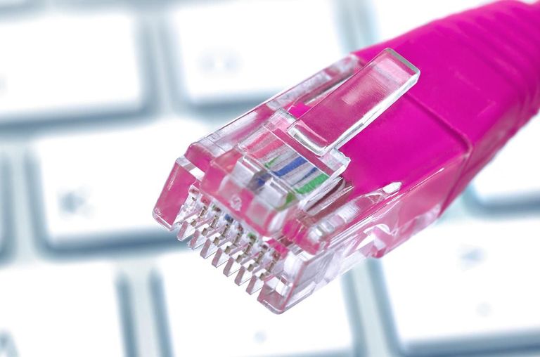
Have you ever noticed the copper cable plugged into your computer? Or to put it specifically, the crystal connector in your computer? That’s what we called RJ45 connector. What is RJ45 connector? It’s a common component used to connect computers into Ethernet-based local area networks (LAN). But how much do you know about this simple connector? Let’s get together to make sense what it looks like and how to terminate Ethernet cable with it.

What Is RJ45 Connector: RJ45 Connector Overview

RJ45 connector is the most common twisted-pair connector for Ethernet cables and networks. The letter “RJ” represents “registered jack” which is a standardized physical network interface for connecting telecommunications or data equipment. RJ45 connector features eight pins for wires to interface, and eight positions, spaced about 1mm apart, into which individual wires are inserted using special cable crimping tools. This type of connector is so-called 8P8C (Eight Position, Eight Contact).

what is rj45 connector

Several other types of connectors closely resemble RJ45, and someone may easily feel confused about them. For example, the RJ11 connector used with telephone cables is one of such connectors. But this connector only uses six positions rather than eight positions, which make them less popular than RJ45 connectors.

Color Coding Diagram of RJ45 Connector

As we all know, when linking RJ45 connector to a cable, there are two wiring standards that define how the RJ45 pinouts to arrange the individual eight wires—the T568A and T568B. With regard to the two standards, there are two different connectivity forms. If both ends of the patch cords are wired on the basis of one standard, it is a straight through connection. If not, it is a crossover connection. Both the standards can be used for straight through cable. Here is an illustration for the color code of RJ45 connectors when they are deployed in different connections.

Straight-Through Connections

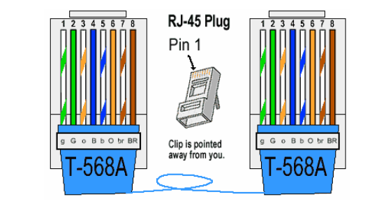
No matter with the standard T-568A or T-568B, once the color order on one end is defined, so does the other end, which means the color order is same on both ends. Take T568A straight through connection for example. The color order of one modular plug is green/white, green, orange/white, blue, blue/white, orange, brown/white and brown. The color order of another modular plug must be corresponding with it (showing as the following picture).

t568a

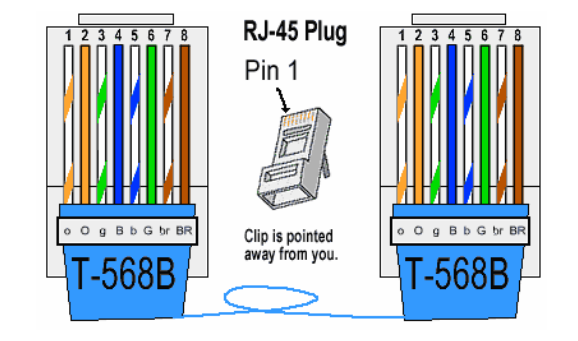
So does the standard T568B. Look at the following picture.

t568b

Crossover Connections

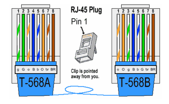
This connection is different from the straight through one, for the color order is different on both ends. It’s no need to spend time remembering how many color orders there may be in this connection. Because you can get a crossover connection by wiring one end using T-568A standard and the other end using T-568B standard. Just like the following picture shows. Or remembering the color coding by simply switching the green set of wires in place with the orange set of wires. Put it in simple terms, switch the green (G) with the orange (O), and switch the green/white with the orange/white.

rj45-crossover-connection

Simple Guidance to Terminate Ethernet Cable With RJ45 Connector

If you have experience to install or maintain cables in LANs, you may know how important to terminate Cat5e, Cat6 or Cat6a copper cables with RJ45 connectors. Mastering this skill sometimes can save time as well as money in Ethernet cable installations. Here is a simple tutorial.

Step one. Trim the end of the Ethernet cable with a crimping tool. Strip off about one inch of the jacket, leaving the twisted pairs outside.

Step two. Separate the 4 twisted wire pairs and unwind each pair. Flatten the wires as much as possible to make preparation for proper individual insertion into the connector.

Step three. Make clear on which standard you are based, then carefully place the wires in order according to that standard.

Step four. Hold the RJ45 connector and carefully insert the prepared wires into the connector, pushing them through the connector until the wire ends come out of the connector’s pin side. Make sure the color order is correct. If not, remove the wires from the connector and do it again.

Step five. Carefully cut the wire ends using crimping tool. Make sure the ends are as flush with the connector’s surface as possible to ensure a good plug-in connection.

Conclusion

This post introduces the basics and color code of RJ45 in different connections as well as how to terminate Ethernet cable with it. As Ethernet systems provide flexible and effective ways to transmit voice and data media, RJ45 connectors, as a key part of Ethernet connectivity, are becoming more popular. Therefore, having a good command of knowledge about it is beneficial.

Related Article: Introduction to Automatically Switched Optical Network (ASON)

CAT5 – Copper Network Solutions Choice

Defined by the Electronic Industries Association and Telecommunications Industry Association (commonly known as EIA/TIA), CAT5 (Category 5) cable is the copper wiring using twisted pair technology, designed for Ethernet networks. The term “Category” refers to the classifications of UTP (unshielded twisted pair) cables. Since its inception in the 1990s, CAT5 has become one of the most popular types of of all twisted pair cable types which include CAT3, CAT4, CAT5, CAT6, etc. This article details CAT5 used in copper networks from its working principles, its standard, as well as its installation considerations.

How CAT5 Cable Technology Works

CAT5 is widely used in 100BASE-TX and 1000BASE-T Ethernet networks. CAT5 typically contains four pairs of copper wire. In 100BASE-TX standard, the signals are transmitted across only two of the CAT5 pairs. One pair is used to transmit signals, and the second pair receives the signals, leaving the other two unused in signal transmission. What’s more, the 100BASE-TX signals only run in one direction across the pairs. As technology advanced, the 1000BASE-T Gigabit Ethernet (GbE) standard was developed. 1000BASE-T standard utilizes all four copper pairs to transmit up to 250 megabits of data per second (Mbps) in full duplex transmission across each pair. That is to say, each pair is able to transmit and receive signals simultaneously. 1000BASE-T modules (eg. GLC-T) functioning over CAT 5 with RJ-45 connector achieve full duplex transmission with link length up to 100m (328ft).

GLC-T, functions over CAT 5 with RJ-45 connector

There are two standards for CAT5 wiring, EIA/TIA-568A and EIA/TIA-568B. The following passages mainly discuss EIA/TIA-568A.

EIA/TIA-568A

The TIA-EIA-568-A standard defined the following three main parameters for testing Category 5 cabling installations: wiremap, attenuation, and Near End Crosstalk (NEXT).

Wiremap is a continuity test. It assures that the conductors that make up the four twisted pairs in the cable are continuous from the termination point of one end of the link to the other. This test assures that the conductors are terminated correctly at each end and that none of the conductor pairs are crossed or short-circuited.

Attenuation is the loss of signal, as it is transmitted from the end of the cable to the opposite end at which it is received. Attenuation, also referred to as Insertion Loss, is measured in decibels (dB). For attenuation, the lower the dB value is, the better the performance is, and of course less signal is lost. This attenuation is typically caused by absorption, reflection, diffusion, scattering, deflection.

Near End Crosstalk (NEXT) measures the amount of signal coupled from one pair to another within the cable caused by radiation emission at the transmitting end.If the crosstalk is great enough, it will interfere with signals received across the circuit. Crosstalk is measured in dB. The higher the dB value, the better the performance, more of the signal is transmitted and less is lost due to coupling.

NEXT: the amount of signal coupled from one pair to another

CAT5 Installation Considerations

After testing parameters are mentioned above, here goes the notes of CAT 5 installation.

  • Never pull CAT5 copper wire with excessive force. The CAT5 tension limitation is 25 lbs, much lower than standard audio/video cable.
  • Never step on, crush, or crimp CAT5.
  • Avoid periodic sags; vary the intervals if the cable must sag.
  • Do not bend CAT5 wire tightly around a corner; ensure that it bends gradually, so that a whole circle would be at least two inches in diameter.
  • Do not allow knots or kinks, even temporarily.
  • Never run CAT5 parallel to power wiring closer than six inches.
  • Avoid splices. Every splice degrades the line.
Conclusion

Although CAT5 is superseded by CAT5e in many applications, most CAT5 cable meets Cat5e standards and it’s still a commonplace in Local Area Networks (LANs). Many copper networks choose CAT5 as their transmission media because of its low price and high performance. Fiberstore supplies many CAT5 RJ45 pluggable modules, like 100BASE-TX, and 1000BASE-T transceivers (eg. SFP-GE-T). For more information about copper network solutions, you can visit Fiberstore.