LAN Switch Used in Network

LAN refers to local area network, which is a network of computers that are in the same general physical location, usually within a building or a campus, share a common communications line or wireless link to a server. Typically, LAN can achieve file management, application software sharing, printer sharing, workgroup scheduling, e-mail and fax communication services and so on. A local area network may serve several hundred users in a larger office, which comprises cables, switches, routers and other components that let users connect to internal servers, websites and other LANs via wide area networks. This post introduces LAN and LAN switch.
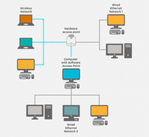
LAN network

Figure 1. LAN Frame

How Does LAN Work?

When two or more network devices have data to send at the same time, the data packets from one user may collide with another, because multiple devices cannot talk on the network simultaneously. For this reason, there should be some methods for the data to access the cable without disturbing another at a time.

Access methods define a set of rules governing how computers access the network – put data onto the network cable and take data from the cable at the same time.This is done in two main methods:

Carrier-Sense Multiple Access with Collision Detection (CSMA/CD)
  • All computers listen for traffic on the LAN.
  • If no traffic, computer that wishes to transmit may transmit data.
  • If a collision occurs, computers must wait a random amount of time.(The busier a network becomes, the more collisions occur)
  • The computer with the smallest random number send again first. (In most cases, a collision will not occur again between the two computers.)
Token Passing
  • All computers need the token which is passed around the network.
  • If a computer has data to send, it must wait until it has the token and then sends its data.
  • When the data transmission is completed, the token is released.
  • It helps to calculate the maximum time when a computer has the chance to send data.
LAN Switch Overview

Switches that provide a separate connection for each computer in the internal network are called LAN switches. Essentially, a LAN switch creates a series of instant networks that contain only the two devices communicating with each other at that particular moment. LAN switches are designed to switch data frames at high speed. LAN switches are the “cornerstone” of building a network platform,which require less configuration, smaller space, fewer cabling, cheaper prices, and higher and more reliable performance.

Switching technologies are crucial to network design that is a form of packet switching used in LAN. LAN switching uses different kinds of network switches. A standard switch is known as a layer 2 switch and is commonly found in nearly any LAN. Layer 3 or layer 4 switches require advanced technology and are more expensive, and thus are usually only found in larger LANs or in special network environments. Here are two main LAN access switches:

S3900-24F4S

S3900-24F4S mode contains one console port that connects to computer for Command Line Interface (CLI) management, four 1GE combo ports, in which RJ45 and SFP ports with same figure are a couple of shared ports, 20 100/1000BASE SFP ports and 4 10GE SFP+ ports.

S3900-24F4S switch

S3900-24T4S

As for S3900-24T4S mode, it offers one console port, 24 100/1000BASE-T ports, and 4 10GE SFP+ ports.

S3900-24T4S switch

S3900-24F4S and S3900-24T4S high-performance gigabit stackable switches are designed to meet the demand for Internet Service Providers (ISPs) and Multiple System Operators (MSOs) to provide home users with triple-play services with up to Gigabit bandwidth, which adopt high performance and low power processor to provide full speed forwarding. Besides, they support multiple configuration modes to make it easy for network management and maintenance and offer flexible port combination form to facilitate user operations so that you can directly connect to a high-performance storage server or deploy a long-distance uplink to another switch.

Outstanding Features of These Switches:
  • Enterprise-Class Features: support advanced Layer 2+ switching and max transfer rate of single port can reach 10GE compared to Layer.
  • High-Capacity Uplinks: every port can be used as the uplink port. SFP+ ports support uplinks of up to 10GE. For high-capacity uplinks, the SFP+ ports can reach 40GE via WEB or order.
  • Switching Capacity: offer 128Gbps switching capacity to simultaneously process traffic on all ports at line rate without any packet loss.
Summary

The network switch plays an integral role in most modern Ethernet LAN because the LAN switch greatly improves the rate of data transmission and the user experience. In addition, LAN switches are the fundamental solutions to help you save time and focus on more strategic initiatives, which provide high-speed connectivity, application, and communication systems that efficiently and securely manage bandwidth-intensive data transmission.

Fundamentals of Power over Ethernet (PoE)

With the introduction of new Ethernet-enabled devices expanding geometrically, the need to power these devices from standard AC power outlets has become a limiting factor. IP phones, wireless access points, IP cameras and device servers are examples of devices limited by the need to have an AC power outlet nearby to plug in a DC power adaptor. At best, power supply installation and wiring add labour and result in the mess of extra wiring; worst case, the lack of nearby AC power means devices cannot be installed where they are needed.

In response to this need, IEEE developed IEEE802.3af to standardise a system of supplying low-voltage power to networked devices via the communications line. It is more commonly referred to as Power over Ethernet (POE). This article focuses on introducing some fundamental elements of PoE.

Basic Concepts of PoE

PoE is defined across a single network link that includes three basic components. The first one is equipment delivering power to the cable (often referred to as a PSE, which stands for power sourcing equipment). The second component is a device receiving power from the cable (also known as a powered device, or PD). The third is the cable itself.

Typical PDs include IP cameras and wireless access points, and the PSE would normally be a PoE switch or a midspan power injector, patched in to add PoE capability to a non-PoE network switch channel or similar. These two configurations are shown in the following picture.

PoE

Advantages of PoE

The most prominent advantages of PoE are time-saving and cost-effective. By reducing the time and expense of having electrical power cabling installed, network cables do not require a qualified electrician to fit them, thus they can be located anywhere. Besides, it has great flexibility. Without being tethered to an electrical outlet, the PDs (IP cameras, wireless access points) could be located wherever they are needed most. Safety is the third advantage. PoE delivery is intelligent and it is designed to protect network equipment from overload, or incorrect installation. Also, it has reliability and scalability. PoE power comes from a central and universally compatible source, rather than a collection of distributed wall adapters. It can be backed up by an uninterruptible power supply, or controlled to easily disable or reset devices.

Applications of PoE

The original PoE application is VoIP phones, which have a single connection to a wall socket and can be remotely powered down, just like with the older analogue systems. PoE could also be used in IP cameras. It is ubiquitous on networked surveillance cameras where it enables fast deployment and easy repositioning. Wifi and Bluetooth APs and RFID (radio frequency identification devices) readers are commonly PoE-compatible, to allow remote locations away from AC outlets, and relocation following site surveys.

How PoE Works

PoE is designed to operate over standard network cable: Cat 5e, Cat 6, Cat 6a or Cat 7 (often collectively referred to as Cat 5e), using conventional RJ45 connectors. The principles of carrying electrical power over Cat5e are of no difference to those of other power distribution systems, but as the power is being transferred over light-duty cable for long distances, the effects of the power loss and voltage drop become significant.

The arrangement and connection to the cabling used for PoE also differ slightly from conventional power wiring, to work around the existing standard for Ethernet data. Cat 5e network cables contain a bundle of eight wires, arranged as four twisted pairs shown in the following picture. In the most common type of Ethernet, 100BASE-T or Fast Ethernet, only two of the four pairs are used to carry data; each pair carrying a signal in one direction. These are known as the data pairs, and the remaining two are unused and are referred to as the spare pairs.

PoE working

Although each data signal can be carried within a single pair, PoE treats each pair of wires as a single conductor (a reason for this is that using both wires halves the overall resistance). As electrical current must flow in a loop, two pairs are required to allow power to be carried by the cable, and either the data or spare pairs can be used for this. The PD must be able to accept power from whichever pairs the PSE delivers it to.

Conclusion

PoE is a convenient and now ubiquitous method for delivering power to a wide variety of loads on standard Cat 5e Ethernet cables. There is no doubt that Power over Ethernet will become increasingly important shortly.