Evolution of Flat, PC, UPC and APC Fiber Connectors

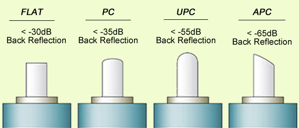
When a connector is installed on the fiber end, loss will be incurred. Some light loss would be reflected back directly down the fiber towards the light source that generated it. These back reflections, or Optical Return Loss (ORL) will damage the laser light sources and also disrupt the transmitted signal. Fiber connectors with different polishing types have different back reflections (see the picture below). With the development of technology, four polishing types are available: flat-surface, Physical Contact (PC), Ultra Physical Contact (UPC), and Angled Physical Contact (APC). How one evolves into another? This article will tell the answer.

polishing type

Flat Fiber Connector

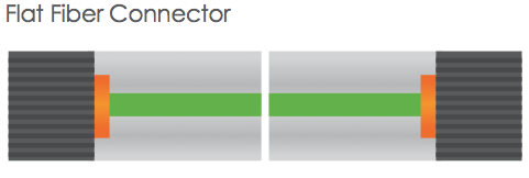
The original fiber connector is a flat-surface connection, or a flat fiber connector. The primary issue of it is that a small air gap between the two ferrules is naturally left when mated. This is partly because the relatively large end-face of the connector allows for numerous slight but significant imperfections to gather on the surface. The flat fiber connector is not suitable for single-mode fiber cables with a 9µm core size, thus it is essential to evolve into Physical Contact (PC) connectors.

flat fiber connector

PC Fiber Connector

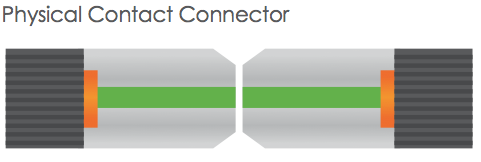
The Physical Contact is polished with a slight spherical design to reduce the overall size of the end-face, which helps to decrease the air gap issue faced by Flat Fiber connectors. It results in lower Optical Return Loss (ORL) with less light being sent back towards the power source.

PC connector

UPC Fiber Connector

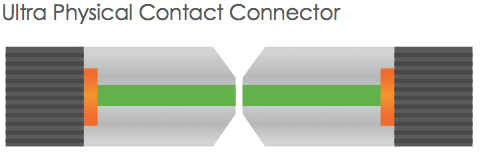
Building on the convex end-face attributes of the PC, but utilizing an extended polishing method creates an even finer fiber surface finish: Ultra Physical Contact (UPC) connector. It has a lower back reflection (ORL) than a standard PC connector and allows more reliable signals in digital TV, telephony and data systems. UPC fiber connector could be used with both single-mode fiber and multimode fiber. Usually the UPC single-mode fiber connector is blue, but the UPC multimode fiber connector is beige. (Note: 10G UPC multimode fiber connector is aqua.)

UPC connector

PC and UPC connectors do have a low insertion loss, but the back reflection (ORL) depends on the the surface finish of the fiber. The finer the fiber grain structure, the lower the back reflection. When PC and UPC connectors are continually mated and unmated, the back reflection will begin to degrade. So there is a need for a connector with low back reflection and it could sustain repeated matings/unmatings without ORL degradation.

APC Fiber Connector

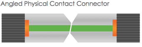
The end faces of Angled Physical Contact connectors are still curved but are angled at an industry standard eight degrees, which allows for even tighter connections and smaller end-face radii. Combined with that, any light that is redirected back towards the source is actually reflected out into the fiber cladding, again by the virtue of the 8°angled end-face. APC connector back reflection does not degrade with repeated matings/unmatings. APC fiber connector can only be used with single-mode fiber and it is green.

APC connector

It is clear that all of the connector end-face options mentioned above take a place in the market. And it is hard to claim that one connector beats the others when your specification needs to consider cost and simplicity not just optical performance. Your particular need decides which one to choose. For those applications calling for high precision optical fiber signaling, APC should be the first consideration, but less sensitive digital systems will perform equally well using UPC. For various connector options, please visit FS.COM.

Related Article: Differences between CWDM and DWDM
How Many Fiber Connector Type Do You Know?

Keep up with the Development in Networks Nowadays

You aren’t by yourself if you have difficulty keeping up with today’s development in networks. There appears to be considered a lot of ruckus over things to get, when you should have it and why. Allow me to assist you to.

The greatest method to transmit data nowadays is with light-based fiber optics instead of the ancient form of electronic signals and the two greatest modules with this would be the SFP and XFP modules, which are a symbol of small form factor placable with X standing for 10 gigabyte. These modules were formed to bring you greater quality from your signal. Additionally, it’s an economical method of providing changeable gigabyte ethernet fiber optic interfaces to switches and hubs that are equipped with a stock SFP slot.

Finding a trusted retailer, and fully knowing optical transceiver modules is going to be helpful when it comes time to create you buy the car. You will have networking questions and concerns. Therefore finding an experienced fiber networking vendor will be crucial. You will have to have the data possible to make a good choice when choosing manufacturers as well as their modules.

Superior optical fibers transport waves of information sent by optical transceiver modules. Modules transport and receive optical signals. Underneath the Multi-Source Agreement, these form factors are made by companies. Specific standards must be met in their building. Transfer speeds are what exactly are accustomed to classify optical transceivers together. Each supports rates from 1Gbps to 10Gbps. Module factors are referred to as SFP and GBIC are 1Gbps. These form factors support transmissions larger than 4Gbps right down to 100mbps. Modules are known as XENPAK, XFP, X2 and SFP support speeds of up to 10Gbps transportation.

10G XENPAK modules are the widest in 10G transceiver interfaces and can include a dual SC fiber interface. Cisco SFP modules can be found in multi-mode and single-mode optical fiber wire, as well as operating in copper wire. 15 meters may be the normal transmission length of a copper module. 300 meters be the transmission reach of multimode lines.

10G XFP transceivers are equipped for 10G network applications, including 10G Ethernet. The conventional for developing these was made by some of the leading manufacturers in the field. Straightforward to care for and change. They’re also small hot plug-hole. This module is utilized in conjunction with laser multimode fibers.

Optical networking solutions are definitely an industry that is constantly on the expand and grow. Their email list above is only a sum of the optical options that you may have to choose from. Once again, choosing the best distributor will be just like crucial as your education of optical transceivers, and how they work. A vendor who sells a broad selection of optical interfaces is going to be helpful. It’s critical they at least have a background experience in all kinds of fiber optical products. This is really crucial if you’re not an expert yourself.

Before you start to play with your new gadget you could try to buy a fiber optic tester to ensure all is in working order and that nothing has been all messed up because of debris or oil. A 20km distance tests are most popular, but try a patch cord if you’re in a bind. Lucent connectors or LC connectors are the resulting fiber ports to connect to the optical modules. Remember, look at and clean the fiber connector prior to plugging in; they cannot work if blocked with even a small piece of debris.

Application of Fiber Optic Connector and Its Terminal Consider Analysis

BNC connectors commonly used with the A/V industry, fiber connector with fiber optic technology continues to mature gradually. Copper connectors on the AV system signal loss generally will not be great, the optical connection is different, its transmission system interface will play a very large effect. Let’s take a look at some of the issues arising in fiber physical connection, fiber optic transmission equipment itself may direct connection, but in some cases, most or almost all of the fiber optic transmission connectivity options are artificially personally. The amount of signal loss by the quality and type of the used optical fiber cable, each connecting end will produce a certain signal is lost. According to the user to select different types of fiber connector, connecting end signal loss add up to the total amount may exceed the amount of fiber optic cable signal loss.

To maintain the normal operation of the system

In the fiber optic system design, the system is capable of normal operation, we achieved very good results, we need to consider some unexpected problems may appear in the system design, and want the system to achieve the effect of normal operation. System design, we have to take into account the worst case may appear and make appropriate plans, looking forward to better operational results. Fiber optic connector design certainly want this idea to heart. In system design, security, stability and system connection requirements the end of the fiber is smooth, Founder. The connection between the client and the client must be precise, micron accuracy or millionths of a meter. Commonly used in the multimode fiber from 50-62.5 microns in diameter, while the diameter of the single-mode fiber is only 8-9 microns. This diameter size of a human hair (17-180 microns) in diameter compared to see any trace of error can bring catastrophic losses.

The fiber optic connection very stringent precision requirements, the connector must be very clean. Fiber optic connectors and accessories are usually mounted on a set of house, a finger print or external dust may seriously affect the performance of the connector, and even lead to transmission failure. Therefore, the connector is not connected, it should be stored in clean protective sleeve in.

In connection, we should also fiber optic connector wedge tight “ferrule” all optical fiber connector design to ensure accurate when the connector with. The optical fiber terminal is inside the ferrule, become a permanent element by adhesive or crimping tight hoop. A built-in optical fiber is inserted, put the ferrule end ground smooth, smooth interface connector fiber optic connection. Ferrules are usually made from a relatively hard material such as ceramic, of course, can also be stainless steel, plastic, or made of a tungsten carbide material, the SC, ST and FC universal ferrule diameter of 2.5mm, the LC common ferrule diameter 1.25mm. Can be due to the functional characteristics of the ferrule to be produced in accordance with the precision requirements, fiber optic connector will become the primary determining characteristics. In connection ferrule, the spring container ferrule guarantee coaxial alignment between the optical fiber and LED or laser source.

With the expansion of technology development and application of fiber optic connectors rapid development. Now in the market the use of optical fiber connector is about 12 or more, each of which is to meet a specific need arises at the historic moment, of course, there are certain technical limitations. Market trend toward a moderate price, compact connector mode development, greater transmission density to support the requirements of the new transmission distribution system. As users expect that the continuous development of the telecommunications industry also contributed to the large scale application of the optical fiber, in large part due to rapid growth in the demand due to the types of communications and entertainment services on the fiber optic connection.

Terminal Consider

Traditionally, fiber optic terminal is generally slower, higher prices are also high, the equipment and technical requirements. Consider fiber singlemode cable terminal, you should take into account several factors. In some cases, we can choose according to various fiber types set up the terminal cable.

The tailor-mount applications, we can only select a specific terminal, but spliced tools, can reduce the length of single-mode fiber-site terminal extension, reduce the number of demand and technology use. For multimode optical fiber cable, spliced new method uses a simple optical fiber cutting method, the cable to be assembled into a pre-designed connector / cable. This method is very simple, just a fiber-to-fiber connector butt joints are usually used a special optical gel fiber terminal condensation.
Source: FiberStore.com