
As we all know , due to the use of the Internet, the data transmission requirements show explosive growth like a geometric progression, so the network transmission speed requirements are also increasing intensity. The multi mode fiber is concerned , due to its inherent properties , it is generally used in a LAN , storage network , data center. In these areas , the data transmission rate of exchange is also required to continue to grow . To Ethernet , for example, since the 1990s , the transmission rate from 10Mbit / s ( Ethernet ) to 100Mbit / s ( Fast Ethernet ). IEEE in 1998 by the IEEE802.3z of Gigabits Ethernet (GbE) standard . 10Gigabit Ethernet standard IEEE802.3ae also passed in June 2002 . Multimode fiber products have been defined by the standard Ethernet transmission medium, its transmission window is at 850nm and 1300nm. Current land use in a communications network products for the general multimode A1a (50/125um) and A1b (62.5/125um) two kinds. Both products are performance and calibration of Ethernet and Fast Ethernet compatible. Just GbE Ethernet and 10GbE Ethernet standard is concerned , A1a and A1b multimode product is not suitable. Mainly due to the modulation frequency of LED (light emitting diode ) light source, only a maximum of about 650MHz. So Gbit / s and 10Gbit / s Ethernet must use LD ( laser diode ) as a light source, such as VCSEL ( vertical cavity surface emitting laser ) light source . This change makes the light A1a and A1b multimode fiber show a mode dispersion problem, the transmission distance can not meet demand. Therefore, it needs to improve the multimode fiber manufacturing technology , development and manufacturing of new generation of multi -mode fiber . This article describes a new generation of technical characteristics and application prospects multimode fiber.
Generally, there are many index to impact multimode fiber performance, but the direct result to the transmission distance is mainly affected by attenuation and multimode fiber bandwidth parameters. The attenuation parameter is determined by the fiber structure and the dopant concentration, the new generation of Multimode Fiber Patch Cable is same with the original fiber optic calbe on the product structure. so they are the same attenuation indicators . Multimode fiber bandwidth uses MHz.km units. It is the modulation frequency and the length of the fiber product of the maximum modulation frequency of the pulse period of the optical fiber which can pass through. Because bandwidth is a comprehensive index multimode fiber characterization of the optical properties, it is affected by many factors, such as the light source, coupling waveguide structure, as well as the receiver performance aside other factors, on the fiber itself, determine its bandwidth intrinsic factor is a multimode fiber dispersion properties. Discussing multimode fiber dispersion analysis generally two ways, i.e., inter- mode dispersion and chromatic dispersion. That is, since the chromatic dispersion of the transmission of different wavelengths of light caused. Mode dispersion refers chromatic dispersion due to the different transmission modes caused. The essential difference between the ordinary and the new generation of multi -mode optical fiber is a multimode optical fiber being derived from this .

Figure 2

For Common multimode fiber, since the LED light source are intended to be used in a network system. LED light source is a wide spectrum of areas having a large output. Due to its broad spectrum of characteristics, emitted light have different wavelength components, when such a light pulse is transmitted in the optical fiber, dispersion is the main cause of chromatic dispersion. The new generation of multi-mode fiber optic network is expected to be used in the LD light source. LD is a single-wavelength laser light source, the LD so emitted light pulse transmitted in the multi-mode fiber, dispersion-mode dispersion will be the main cause.
The related proucts about Common Multi-mode Fiber Optic Cable from Fiberstore, SC-SC Simplex 62.5/125 OM1 Multimode Fiber Optic Cable,
At the same time, because the common manufacturing process multimode fiber defects appear in the center of the center “recess”, this defect is due to the dopant material, such as a transition caused by evaporation of germanium. While multimode fiber interface, i.e., between the fiber core and cladding is easy due to the diffusion of dopant materials such defects. These defects in the original multi-mode fiber is not important. But for a new generation of multi-mode fiber is fatal. These defects will greatly increase the inter-mode dispersion and reduce the transmission properties of the optical fiber.
For the light source, the table 1 is a comparison of a typical LED light source and a VCSEL. it can be found, VCSEL is much less than the spectral width of the spectral width of the LED, so the purpose of comparison to the LED, LD can be said that the injection of a single wavelength. The LED and light emitted from the LD of different spot size. LED exit a larger area, you can inspire all of multimode fiber conduction mode, while LD light spot emitted only a small part inspired conduction mode. When injected into the LD multi-mode fiber end faces at different locations, different mode groups are excited, it will make the inter-mode dispersion and a greater difference between the transmission distance of the impact pulse. Figure 4 shows a comparison of light output LED and a VCSEL.
Injection method means the energy emitted by the light source is coupled into the multimode fiber process. Generally limited to full injection and injection molded in two ways. When the LED light source is a full injection, i.e., spot size, and light emitted from the multimode fiber core sizes are matched, then the pulse is excited in the multimode fiber optic cable conduction mode transmission, the transmission energy is concentrated in the middle mode group. While limiting the injection mold, the incident light spot covers only a part of the core, when it is conducting, it is only part of the excitation conduction mode groups. When the incident light spot at different positions of the core, the excited mode groups are different, resulting in differences in the inter-modal dispersion such that the bandwidth performance of the change of the transmission fiber. Therefore, when injected into the mold limit, you must determine the position and angle of the incident, otherwise the transmission distance of fiber support will change.
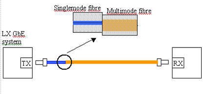
In IEEE802.3z GbE Ethernet standard, for the laying of fiber optic cable has proposed a so-called Patch cord [4] solution is injected into the mold of a typical limit program. In the 1300nm wavelength, this solution uses a single mode fiber as shown bias limit injection molding conditions, this Single Mode Fiber Cable can not only reduce multi-mode fiber optic which conduction mode is excited, but also partial connection set. It can avoid larger centers may exist in the optical fiber embedded in a recess problems.
The above shows that the use of ordinary multimode fiber at Gbit / s and 1010Gbit / s Ethernet system, the light source, injection method and fiber itself, it will greatly deteriorate the performance of optical fiber transmission, increase system overhead, or increase system complexity. To solve these problems, the development of a new generation of suitable Gbit / s transmission rate over multimode fiber using a local area network products are the best choice. The new generation multimode fiber products from Fiberstore, you can find the related products, MPO MTP Fiber. MPO/MTP Fiber Cable is offered for many applications for all networking and device needs like 100 Gig modules. MPO Fiber Cable From Fiberstore are available in UPC and APC finishes, it supports both multimode and single mode applications, and optional lengths available. Our MPO/MTP fiber cable is with push connector IEC 61754-7 and TIA/EIA 604-5A compliant and offer low cost per termination for high density applications.