
With the development of technology, no matter how far you are away from families, you can communicate with them at any time in any places. The same is true to the optic communication, regardless of the physical locations of two hosts or the different VLANs they belong to, they can exchange with each other by inter VLAN routing. Then what is inter VLAN routing and how to configure inter VLAN routing on layer 3 switches?
What Is Inter VLAN Routing?
In figure 1, three computers connected to a gigabit Ethernet switch form a LAN (local area network) within a limited area. However, they cannot communicate with hosts in another LAN, because there is no connection between these Ethernet switches. Then there comes the VLAN which provides us with logical separation or segmentation of our networks to facilitate communication among hosts in different LANs. However, each VLAN is a unique broadcast domain, so computers on separate VLANs are unable to communicate with each other by default. There is a way to solve the problem, and that’s what we are going to shed light on—inter VLAN routing.
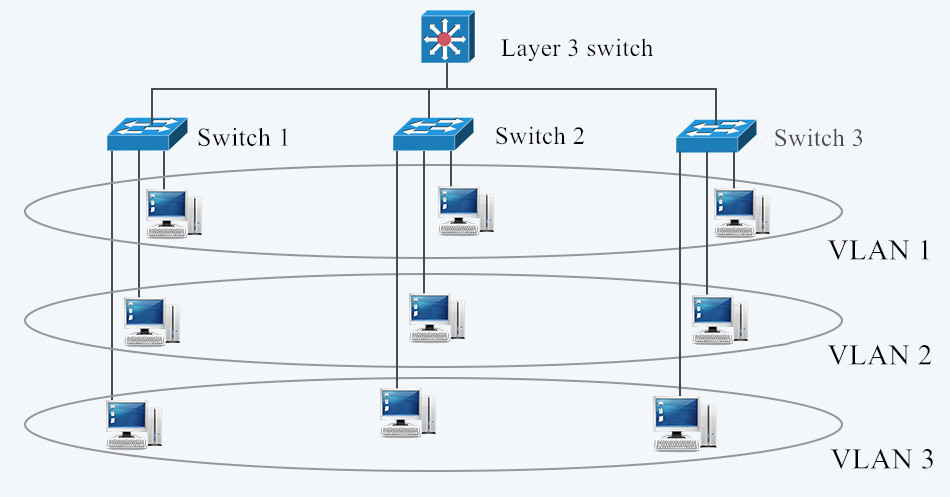 Fig. 1 LAN and VLAN in Networking
The process of forwarding network traffic from one VLAN to another VLAN using routing is known as inter-VLAN routing. One of the ways to carry out inter-VLAN routing is by connecting a router to the switch infrastructure. When using a router to facilitate inter-VLAN routing, the router interfaces can be connected to separate VLANs. Devices on those VLANs communicate with each other via the router. Apart from that, a more convenient way is introduced—configure inter VLAN routing on layer 3 switches. Layer 3 switching is more scalable than a router which only provides a limited number of available ports.
How to Configure Inter VLAN Routing on Layer 3 Switches?
To enable a layer 3 switch to perform routing functions, the switch must have IP routing enabled. 10gb Ethernet switch and 40gb Ethernet switch are recommended for working as layer 3 switch.
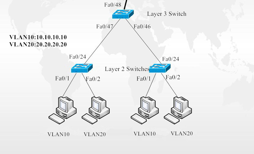
Fig.2 Inter VLAN Routing on Layer 3 Switches
In figure 2, layer 3 switch is configured with IP address 10.0.0.1. VLAN10 and VLAN20, with IP address 10.10.10.10 and IP address 10.20.20.20 respectively are configured on layer 2 switches. These two IP addresses will be the default gateway addresses for hosts belonging to VLAN10 and VLAN20 on the layer 2 switches respectively. Also, all interfaces connecting the three switches must be configured as trunk ports to allow VLAN10 and VLAN20 tagged frames to pass between switches. Traffic between VLAN10 and VLAN20 will be routed by the layer 3 switch after configuring inter VLAN routing. These steps can be achieved by VLAN configuration command below.
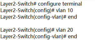
Create VLANs 10 and 20 in the switch database
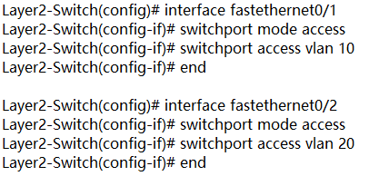
Assign port Fe0/1 in VLAN 10 and port Fe0/2 in VLAN 20

Enable layer 3 routing and create VLANs 10 and 20 in the switch database

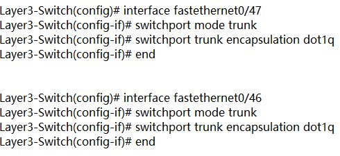
Create trunk ports Fe0/47 Fe0/46
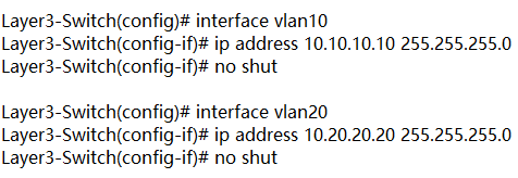
Configure Switch VLAN Interfaces (SVI) to acts as a virtual layer 3 interface on the layer 3 switch
Conclusion
VLAN is created to enable the communication among hosts in different LANs. Inter VLAN routing is developed to realize the exchange among hosts in different VLANs. Inter VLAN routing on layer 3 switch without a router is also approachable with the development of technology. For more configuration about network switches, please refer to our website www.fs.com.