
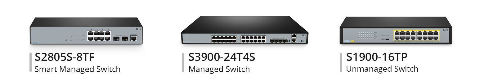
Switches form the backbone of LANs, efficiently connecting devices within a specific LAN and ensuring effective data transmission among them. There are three main types of switches: managed switches, smart managed switches, and unmanaged switches. Choosing the right switch during network infrastructure upgrades can be challenging. In this article, we delve into the differences between these three types of switches to help determine which one can meet your actual network requirements.
What are Managed Switches, Unmanaged Switches and Smart Switches?
Managed switches typically use SNMP protocol, allowing users to monitor the switch and its port statuses, enabling them to read throughput, port utilisation, etc. These switches are designed and configured for high workloads, high traffic, and custom deployments. In large data centres and enterprise networks, managed switches are often used in the core layer of the network.
Unmanaged switches, also known as dumb switches, are plug-and-play devices with no remote configuration, management, or monitoring options. You cannot log in to an unmanaged switch or read any port utilisation or throughput of the devices. However, unmanaged switches are easy to set up and are used in small networks or adding temporary device groups to large networks to expand Ethernet port counts and connect network hotspots or edge devices to small independent networks.
Smart managed switches are managed through a web browser, allowing users to maintain their network through intuitive guidance. These smart Ethernet switches are particularly suitable for enterprises needing remote secure management and troubleshooting, enabling network administrators to monitor and control traffic for optimal network performance and reliability. Web smart managed switches have become a viable solution for small and medium-sized enterprises, with the advantage of being able to change the switch configuration to meet specific network requirements.
What is the Difference Between Them?
Next, we will elaborate on the differences between these three types of switches from the following three aspects to help you lay the groundwork for purchasing.
Configuration and Network Performance
Managed switches allow administrators to configure, monitor, and manage them through interfaces such as Command Line Interface (CLI), web interface, or SNMP. They support advanced features like VLAN segmentation, network monitoring, traffic control, protocol support, etc. Additionally, their advanced features enable users to recover data in case of device or network failures. On the other hand, unmanaged switches come with pre-installed configurations that prevent you from making changes to the network and do not support any form of configuration or management. Smart managed switches, positioned between managed and unmanaged switches, offer partial management features such as VLANs, QoS, etc., but their configuration and management options are not as extensive as fully managed switches and are typically done through a web interface.
Security Features
The advanced features of managed switches help identify and swiftly eliminate active threats while protecting and controlling data. Unmanaged switches do not provide any security features. In contrast, smart managed switches, while also offering some security features, usually do not match the comprehensiveness or sophistication of managed switches.
Cost
Due to the lack of management features, unmanaged switches are the least expensive. Managed switches typically have the highest prices due to the advanced features and management capabilities they provide. Smart managed switches, however, tend to be lower in cost compared to fully managed switches.
| Features | Performance | Security | Cost | Application | |
|---|---|---|---|---|---|
| Managed Switch | Comprehensive functions | Monitoring and controlling a whole network | High-levels of network security | Expensive | Data center, large size enterprise networks |
| Smart Managed Switch | Limited but intelligent functions | Intelligent manage via a Web browser | Better network security | Cheap | SMBs, home offices |
| Unmanaged Switch | Fixed configuration | Plug and play with limited configuration | No security capabilities | Affordable | Home, conference rooms |
How to Select the Appropriate Switch?
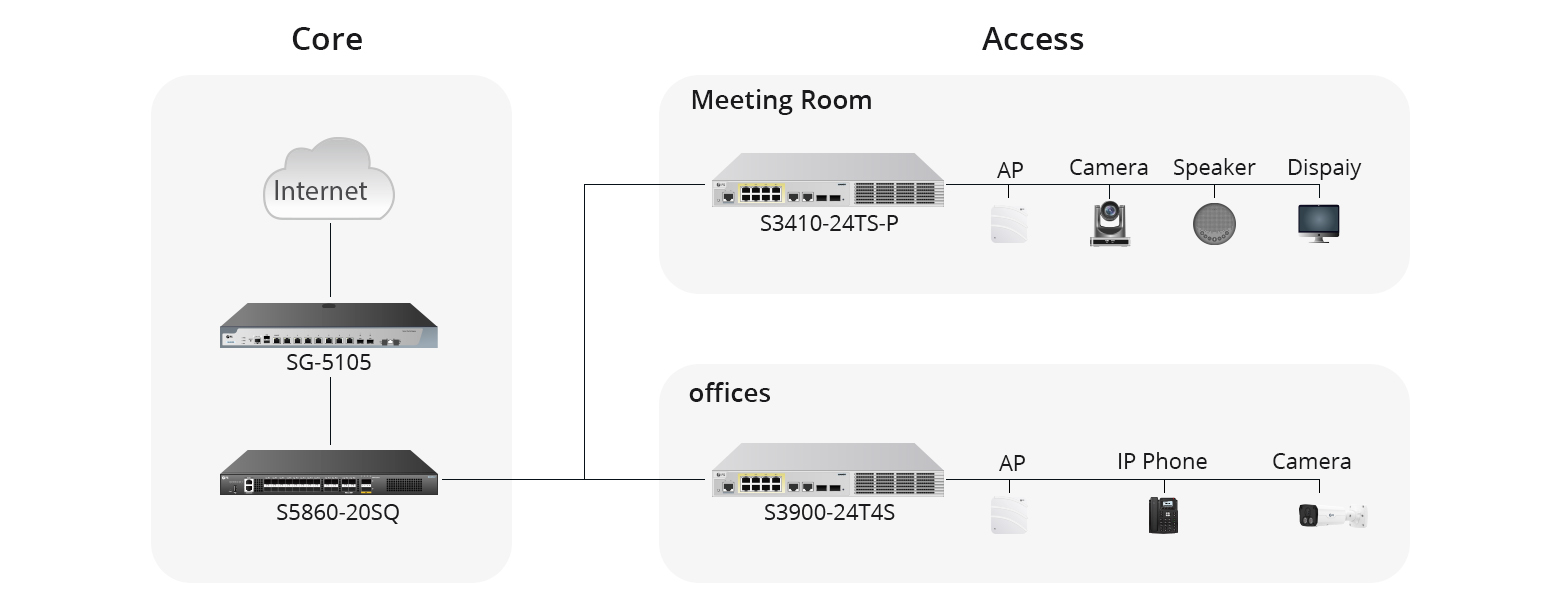
After understanding the main differences between managed, unmanaged, and smart managed switches, you should choose the appropriate switch type based on your actual needs. Here are the applications of these three types of switches, which you can consider when making a purchase:
- Managed switches are suitable for environments that require highly customised and precise network management, such as large enterprise networks, data centres, or scenarios requiring complex network policies and security controls.
- Smart managed switches are suitable for small and medium-sized enterprises or departmental networks that require a certain level of network management and flexible configuration but may not have the resources or need to maintain the complex settings of a fully managed switch.
- Unmanaged switches are ideal for home use, small offices, or any simple network environment that does not require complex configuration and management. Unmanaged switches are the ideal choice when the budget is limited, and network requirements are straightforward.
In brief, the choice of switch type depends on your network requirements, budget, and how much time you are willing to invest in network management. If you need high control and customisation capabilities, a managed switch is the best choice. If you are looking for cost-effectiveness and a certain level of control, a smart managed switch may be more suitable. For the most basic network needs, an unmanaged switch provides a simpler and more economical solution.
Conclusion
Ultimately, selecting the appropriate switch type is essential to achieve optimal network performance and efficiency. It is important to consider your network requirements, budget, and management preferences when making this decision for your network infrastructure.
As a leading global provider of networking products and solutions, FS not only offers many types of switches, but also customised solutions for your business network. For more product or technology-related knowledge, you can visit FS Community.

.jpg)
-1.jpg)