Planar Lightwave Circuit (PLC) Based Optic Power Splitter

In a power-splitting PON, an optical power splitter is the passive device in the outside plant that physically connects to the CO with a feeder fiber. It also connects to a number of ONUs via a series of distribution fibers. In the past few years, significant improvements in reliability, cost per port, insertion loss, and splitting-ratio nonuniformity, have been demonstrated with planar lightwave circuit (PLC)-based splitters. Central to the splitter is a PLC chip comprising of optical waveguides fabricated on a planar substrate, typically made of silicon or quartz, to form a cascade of Y-branches. For a 1 × splitter, one side of the PLC chip is aligned to a fiber whereas the opposite side is aligned to an array of PON is typically N = 16 and N = 325, but with an increasing demand of up to N = 64, thereby making the alignment of the fiber array to the PLC chip more challenging. Compared to fused biconical-taper-based splitters, PLC technology allows for chip-size devices with the potential of integrating multiple functions, e.g. WDM coupler, onto a single clip. It also enables a more uniform loss over a wide operating range of wavelengths from 1250 nm to 1625 nm, and operaton of a wide range of temeratures from -40℃ to + 80℃. Figure 3.2 illustrates the measured insertion losses from samples of 1×32 optical splitter approved by AT&T Labs for use in the Project Lightspeed FTTH trial, showing uniform loss over a wide wavelength range.

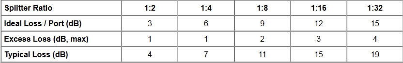
Aside from uniform loss, the insertion loss of PLC splitters is another important parameter in network implementations that will influence system performance and the overall coast per drop. Lower insertion loss PLC slitters will extend the reach and number of customers that can be accommodated within the same PON, yielding higher revenue per PON for service providers. Aside of the theoretical splitting loss attributed to the division of optical power at the input port equally into N output ports, and given by the fromula:

Theoretical splitting loss (dB) = 10 × log10(1/N)

A PLC splitter suffers from excess insertion loss from fiber array alignment to the PLC chip, fiber array uniformity caused by pitch and depth inaccuracies in the v-grooves of fiber array block that holds the fiber array, splitting ratio uniformity caused by imperfections in the PLC chip due to manufacturing, inherent chip material loss, and inherent chip material loss, and connector loss. The targeted areas for improvement of insertion loss in PLC splitters have been in reducing connector losses, and improving fiber array and splitting ration-nonuniformity. The connector loss can be improved from 0.5 dB trough using high quality ferrules and an excellent polishing method. With advances in manufacturing process of the fiber array block and PLC chip, insertion losses from fiber array nonuniformity and splitting-ratio nouniformity can be reduced from 0.7 dB to 0.4 dB and 1.8 dB to 1.0 dB, respectively. Collectively, the excess insertion losses of PLC splitters are currently 1 – 1.5 dB above the ideal theoretical splitting loss with a nonuniformity within 2 dB over the specified range of operating wavelengths from 1250 nm to 1625 nm.

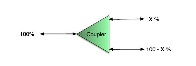
Fiber optical splitter is used to split the fiber optic light into several parts at a certain ratio . The fiber optic splitter is an important passive component used in PON FTTX networks. There are mainly two kinds of passive FTTH optical splitters: one is the traditional fused type splitter as known as FBT coupler or FBT WDM optical splitter, which features competitive price; the other is the PLC splitter based on the PLC (Planar Lightwave Circuit) technology, which has a compact size and suits for density applications. The common PLC Splitters configurations are 1×4, 1×8, 1×16, 1×32, 1×64 and 1×128, but 2×4, 2×8, 2×16, 2×32 configurations are also available.  Fiberstore singlemode& multimode FBT optical splitter comes in a wide range of split ratios with single/double/three windows. The main packages include box type and stainless tube type. The former is usually used with 2mm or 3mm outer diameter cable, while the latter is usually used with 0.9mm outer diameter cable. Our optical splitter can be terminated with your choice of connectors or installed in rack mount modules. Please contact us for the special customized needs.

A Comparison between Tee Coupler and Star Coupler

In many applications, it may not be possible to have a design of many point-to-point connections. In these cases, optical couplers are used. A fiber optic coupler is a device that combines or splits optical signals. A coupling device may combine two or more optical signals into a single output, or the coupler may be used to take a single optical input and distribute it to two or more separate outputs. The Figure below shows an example of a basic four-port coupler, generally named fiber coupler 1 × 4.

4-Port Coupler

Many couplers are designed bidirectionally, which enables the same coupler to be used to combine signals or split signals. An optical coupler being used to split a signal may be referred to as an optical splitter. Couplers are available with a wide range of input and output ports. A basic coupler may have only one input port and two output ports. Today’s technology supports couplers with up to 64 input and 64 output ports, as shown below.

128-Port Coupler

There are many different types of couplers, and the number of input and output ports is dependent on the intended usage. Some of the types of optical couplers are optical combiners, Y couplers, star couplers, tee couplers, and optical splitters. In this article, we will only focus on the tee coupler and the star coupler and give you a comparison between them.


Tee Coupler

A tee coupler is a three-port optical coupling device that has one input port and two output ports, as shown below.

Tee Coupler

The tee coupler is a passive device that splits the optical power from the input port into two output ports. The tee coupler is in essence an optical splitter. The uniqueness of the tee coupler is that this type of coupler typically distributes most of the optical input power to one output and only a small amount of power to the secondary output. Note that when the outputs are evenly distributed, the coupler is called a Y coupler. The tee coupler is also referred to as an optical tap, due to the nature of the device. A majority of the power continues forward, but a portion of the signal (determined by the splitting ratio) is tapped to be used for an output port.

The tee coupler is a 1 × 2 coupler or 1 × 2 fiber splitter, meaning that it has one input port (or connection) and two output ports. As previously stated, the optical output power of the two output ports is typically not evenly distributed. Common splitting ratios are 90:10, 80:20, 70:30, 60:40, and 50:50 (a Y coupler). Not all manufacturers follow the convention of placing the larger value to the left of the colon and the smaller to the right. Some manufacturers simply reverse this and place the smaller value to the left of the colon and the larger to the right.

A typical use for a tee coupler would be to supply optical signals to a bus type network of in-line terminals. Assuming ideal conditions and a 90:10 split on the tee coupler, the first terminal would receive 10 percent of the optical signal and 90 percent of the optical signal would go forward to the next tee coupler.


Star Coupler

The star coupler is used in applications that require multiple ports (input and/or output). The star coupler will distribute optical power equally from one or more input ports to two or more output ports. Here is a basic star coupler with four input ports and four output ports. Star couplers are available in 1 × 64 up to 64 × 64 dimensions.

8-Port Star Coupler

A special version of the star coupler, called a tree coupler, is used when there is one input port and multiple output ports or when there are multiple input ports and one output port.

Star couplers are frequently used in network applications when there are a large number of output terminals. In our tee coupler example, we had to account for interconnection insertion loss and coupler insertion loss at each tee connection. However, with the star coupler there is only one coupler insertion loss regardless of the number of ports. With only one coupler insertion loss, a multiple port star coupler is more efficient than a series of tee couplers. So the larger the network is, the more efficient the star coupler becomes.

Two types of star couplers are commonly used: the reflective star and the transmissive star. Couplers are typically considered to be a black box, that is, only the manufacturer knows what’s inside. However, many star couplers are made of fused optical fibers as a type of fused fiber coupler.


Advantages of Star Coupler compared to Tee Coupler

The key advantage to the star coupler is that there is only one insertion loss caused by the coupler. The only remaining insertion losses are from the interconnections. The advantage of the star coupler becomes very apparent as the number of ports increases. Here is a simple loss-comparison chart that reveals the significance in the number of terminals versus loss for the tee and star couplers.

Real Tee Coupler VS. Real Star Coupler Comparison Chart

A star coupler has another advantage over a series of tee couplers. If one of the tee couplers in the series is disconnected, none of the other terminals down the line will receive an optical signal. However, disconnecting a terminal from the star coupler will not impact the operation of the other terminals.

Related Article: Overview of Bi-Directional Transceiver Modules

Testing Fiber Optic Splitters Or Other Passive Devices

A fiber optic splitter is a device that splits the fiber optic light into several parts by a certain ratio. For example, when a beam of fiber optic light transmitted from a 1X4 equal ratio splitter, it will be divided into 4-fiber optic light by equal ratio that is each beam is 1/4 or 25% of the original source one. A Optical Splitter is different from WDM. WDM can divide the different wavelength fiber optic light into different channels. fiber optic splitter divide the light power and send it to different channels.

Most Splitters available in 900µm loose tube and 250µm bare fiber. 1×2 and 2×2 couplers come standard with a protective metal sleeve to cover the split. Higher output counts are built with a box to protect the splitting components.

Testing a coupler or splitter (both names are used for the same device) or other passive fiber optic devices like switches is little different from testing a patchcord or cable plant using the two industry standard tests, OFSTP-14 for double-ended loss (connectors on both ends) or FOTP-171 for single-ended testing.

First we should define what these passive devices are. An optical coupler is a passive device that can split or combine signals in optical fibers. They are named by the number of inputs and outputs, so a splitter with one input and 2 outputs is a 1×2 fiber splitter, and a PON splitter with one input and 32 outputs is 1×32 splitter. Some PON splitters have two inputs so it would be a 2X32. Here is a table of typical losses for splitters.

Splitter Ratio

Important Note! Mode Conditioning can be very important to testing couplers. Some of the ways they are manufactured make them very sensitive to mode conditioning, especially multimode but even singlemode couplers. Singlemode couplers should always be tested with a small loop in the launch cable (tied down so it does not change and set the 0dB reference with the loop.) Multimode couplers should be mode conditioned by a mandrel wrap or similar to ensure consistency.

Let’s start with the simplest type. Shown below is a simple 1X2 splitter with one input and two outputs. Basically, in one direction it splits the signal into 2 parts to couple to two fibers. If the split is equal, each fiber will carry a signal that is 3dB less than the input (3dB being a factor of two) plus some excess loss in the coupler and perhaps the connectors on the splitter module. Going the other direction, signals in either fiber will be combined into the one fiber on the other side. The loss is this direction is a function of how the coupler is made. Some couplers are made by twisting two fibers together and fusing them in high heat, so the coupler is really a 2X2 coupler in which case the loss is the same (3dB plus excess loss) in either direction. Some splitters use optical integrated components, so they can be true splitters and the loss in each direction may different.

coupler

So for this simple 1X2 splitter, how do we test it? Simply follow the same directions for a double-ended loss test. Attach a launch reference cable to the test source of the proper wavelength (some splitters are wavelength dependent), calibrate the output of the launch cable with the meter to set the 0dB reference, attach to the source launch to the splitter, attach a receive launch cable to the output and the meter and measure loss. What you are measuring is the loss of the splitter due to the split ratio, excess loss from the manufacturing process used to make the splitter and the input and output connectors. So the loss you measure is the loss you can expect when you plug the splitter into a cable plant.

To test the loss to the second port, simply move the receive cable to the other port and read the loss from the meter. This same method works with typical PON splitters that are 1 input and 32 outputs. Set the source up on the input and use the meter and reference cable to test each output port in turn.

What about the other direction from all the output ports? (In PON terms, we call that upstream and the other way from the 1 to 32 ports direction downstream.) Simply reverse the direction of the test. If you are tesing a 1X2 splitter, there is just one other port to test, but with a 1X32, you have to move the source 32 times and record the results on the meter.

fiber splitter

What about multiple input and outputs, for example a 2X2 coupler? You would need to test from one input port to the two outputs, then from the other input port to each of the two outputs. This involves a lot of data sometimes but it needs to be tested.

There are other tests that can be performed, including wavelength variations (test at several wavelengths), variations among outputs (compare outputs) and even crosstalk (put a signal on one output and look for signal on other outputs.)

Once installed, the splitter simply becomes one source of loss in the cable plant and is tested as part of that cable plant loss for insertion loss testing. Testing splitters with an OTDR is not the same in each direction。

Other Passive Devices

There are other passive devices that require testing, but the test methods are similar.

Fiber optic switches are devices that can switch an input to one of several outputs under electronic control. Test as you would the splitter as shown above. Switches may be designed for use in only one direction, so check the device specifications to ensure you test in the proper direction. Switches may also need testing for consistency after multiple switch cycles and crosstalk.

Attenuators are used to reduce signal levels at the receiver to prevent overloading the receiver. There is a page on using attenuators that you should read. If you need to test an attenuator alone, not part of a system, use the test for splitters above by using the attenuator to connect the launch and receive cables to see if the loss is as expected.

Wavelength-division multiplexers can be tricky to test because they require sources at a precise wavelenth and spectral width, but otherwise the test procedures are similar to other passive components.

Fiber optic couplers or splitters are available in a wide range of styles and sizes to split or combine light with minimal loss. All couplers are manufactured using a very simple proprietary process that produces reliable, low-cost devices. They are physically rugged and insensitive to operating temperatures. Couplers can be fabricated in custom fiber lengths and/or with terminations of any type.

Fiberstore offers a wide variety of collimation and coupling components that can be used to effectively collimate or couple light out of and into FC/PC, FC/APC, or SMA terminated fiber. Optical isolators help protect sensitive laser sources and components from back reflections while fiber couplers, WDMs, circulators, and switches are the fundamental tools to creating fiber based optical circuits. We also offer a line of components for optogenetics applications, including fiber optic cannulae, patch cords, and light sources.

Buy Bare Fiber PLC Splitter From FiberStore

Bare fiber PLC splitter is an optical power management device which is widely used in PON networks to realize optical signal power splitting. The common configurations are 1×4, 1×8, 1×16, 1×32 and 1×64 PLC Splitters, but 2×4, 2×8, 2×16, 2×32 configurations are also available. Bare Fiber PLC Splitter comes with unterminated ends so that it can be fused by customers themselves.

Planar Lightwave Circuit (PLC) splitter, PLC splitters are used to distribute or combine optical signals. It is based on planar lightwave circuit technology and provides a low cost light distribution solution with small form factor and high reliability. 1xN PLC splitters are precision aligning process to divide a single optical input(s) into multiple optical outputs uniformly,while 2xN PLC splitters divide a dual optical input(s) into multiple optical outputs. FiberStore PLC splitters offer superior optical performance, high stability and high reliability to meet various application requirements.

The bare PLC splitters are used for small spaces that can be easily placed in a formal joint boxes and splice closure. In order to facilitate welding, it does not need specially designed for space reserved.

FiberStore provides a various of 1xN and 2xN PLC bare splitters, including 1×2, 1×4, 1×8, 1×16,1×32, 1×64 bare fiber type PLC splitter and 2×2, 2×4, 2×8, 2×16, 2×32 bare fiber type PLC splitters.

Bare Fiber Type PLC Splitter Features
  • Good uniformity and low insertion loss
  • Low Polarization Dependent Loss
  • Excellent Mechanical
  • Stability Telecordia GR-1221 and GR-1209
  • Components through TLC-Certified,Conform to YD1117-2001
  • Operating environment: -40ºC to +85ºC
  • High Polarization Extinction Ratio & Excellent Uniformity
  • Fiber input: 0.9um loose tube or 250um bare fiber for choice
  • Fiber output: 250um bare fiber (It is benefit for splicing)
Bare Fiber Type PLC Splitter Applications
  • Fiber to the point (FTTX)
  • Fiber to the home (FTTH)
  • Passive optical networks(PON, GEPON)
  • Local area networks (LAN)
  • Cable television (CATV)
  • Test equipment
Mechanical Drawing

Kind note: This price is without connector

V.S FBT Coupler, the advantages of PLC are as follows
  • The loss to different wavelength transmission is not sensitive, so it can meet the transmission requirements of different wavelength
  • High spectral uniformity, can splitter the signals on average
  • Compact structure, small volume
  • The cost advantage is very obvious on many splitter channels
Order Information

FiberStore provides a whole series of 1xN and 2xN splitters that are tailored for specific applications:

a.1×2, 1×4, 1×8, 1×16,1×32, 1×64, 2×2, 2×4, 2×8, 2×16, 2×32 Versions of splitters are available.

b. SC/UPC, FC/UPC, LC/UPC, SC/APC, FC/APC, LC/APC connectors or no connectors can be selected as you like

c. 250um bare fiber or 0.9 mm loose tube can be choose as input fiber type, 250um bare fiber for output fiber type.

d. The length of pigtail can be also customized; usually we will provide you 1.5m, welcome to contact us for more details.

Sample Pictures


FiberStore also supply other fiber optic products, such as mpo connectorfiber attenuators, Ethernet to fibre optic converter and more. If you would like to purchase our plc splitters, please contact us.

Introduction To Fiber Optic Couplers

A fiber optic coupler is a device used in fiber optic systems with single or more input fibers and single or several output fibers, which is different from WDM  devices. WDM multiplexer and demultiplexer divide the different wavelength fiber light into different channels, while fiber optic couplers divide the light power and send it to different channel.

Bandwidth
Most types of couplers work only in a limited range of wavelength (a limited bandwidth), since the coupling strength is wavelength-dependent (and often also polarization-dependent). This is a typical property of those couplers where the coupling occurs over a certain length. Typical bandwidths of fused couplers are a few tens of nanometers. In high-power fiber lasers and amplifiers, multimode fiber couplers are often used for combining the radiation of several laser diodes and sending them into inner cladding of the active fiber.

Structure
A basic fiber optic coupler has N input ports and M output ports. N and M typically range from 1 to 64. M is the number of input ports (one or more). N is the number of output ports and is always equal to or greater than M. The number of input ports and output ports vary depending on the intended application for the coupler.

Light from an input fiber can appear at one or more outputs, with the power distribution potentially depending on the wavelength and polarization. Such couplers can be fabricated in different ways:
Some couplers use side-polished fibers, providing access to the fiber core;
Couplers can also be made from bulk optics, for example in the form of microlenses and beam splitters, which can be coupled to fibers (“fiber pig-tailed”).

Types
Fiber optic couplers can either be passive or active devices. Passive fiber optic couplers are simple fiber optic components that are used to redirect light waves. Passive couplers either use micro-lenses, graded-refractive-index (GRIN) rods and beam splitters, optical mixers, or splice and fuse the core of the optical fibers together. Active fiber optic couplers require an external power source. They receive input signals, and then use a combination of fiber optic detectors, optical-to-electrical converters, and light sources to transmit fiber optic signals.

Types of fiber optic couplers include optical splitters, optical combiners, X couplers, star couplers, and tree couplers. The device allows the transmission of light waves through multiple paths.

Fused couplers are used to split optical signals between two fibers, or to combine optical signals from two fibers into one fiber. They are constructed by fusing and tapering two fibers together. This method provides a simple, rugged, and compact method of splitting and combining optical signals. Typical excess losses are as low as 0.2dB, while splitting ratios are accurate to within ±5 percent at the design wavelength. The devices are bi-directional, and offer low backreflection. The technique is best suited to singlemode and multimode couplers.

Choices for fiber optic coupler also include Single window narrow band, Single window Wide band, and Dual window Wide band fiber optic coupler. Single window fiber optic coupler is with one working wavelength. Dual window fiber optic coupler is with two working wavelength. For Single mode fiber, is optimized for 1310 nm and 1550 nm; For Multimode fiber, is optimized for 850 nm and 1310 nm.

FBT splitter And PLC Splitter For Sale In Fiberstore

As the optical fiber communication industry recovery and the development of FTTX, fiber optic coupler splitter market in the spring is coming. Optical divider at present basically has two types: one is the traditional optical passive components production technology (FBT splitter) production of fused taper fiber divider; Another is to use an integrated optical technology production of planar optical waveguide branching device (PLC).Basically the two type of fiber splitter share the similar spectroscopic principle. Both of them are coupled to each other by changing the optical fiber between the evanescent field (the degree of coupling, the coupling length) as well as to change the radius of the optical slender to achieve different size branching amount.Fiberstore supply the FBT splitter and PLC Splitter.You can find them in our store.

FBT splitter

FBT splitter based on the traditional technology, it is to bundle together two or more optical fibers, and then pull the cone machine melt stretching, and real-time monitoring the change of the ratio, spectral ratio requirements after melt stretching, one side retain a single fiber (the rest of the cut) as input, the other end is a multi-channel output. At present mature pull cone process once only 1 x 4 below. More than 1 x 4 devices, with more than 1 x 2 together. Overall packaging again in the divider boxes.FBT Coupler is designed for power splitting and tapping telecommunication equipment, CATV networks, and test equipment.

Due to the making method of the FBT Coupler is simple, inexpensive, easy to connect to external fiber as a whole, and resistance in for-mechanical vibration and temperature changes, and other advantages, it has become the mainstream manufacturing technology in current the market.

PLC Splitter

PLC Splitter is a hot research at home and abroad today, with a good prospect of application,PLC Splitter (Planar waveguide Circuit optical splitter) are developed using silica glass waveguide circuits and aligned fiber pigtails, integrated inside a miniature package. PLC splitters provide low-cost solution for optical signal distribution, with small form factor and superb reliability. They are designed for FTTx Passive Optical Networks, CWDM, DWDM and optical cable TV System. For example,the blockless plc splitter module is one of PLC Splitter,it uses PLC & Package technology to split one wavelength into many ports, from 4 way to 32 way. It has no fan-out block so you can save space and achieve smaller splitter modules.

Advantages

FBT splitter: Low cost, raw materials gotten easily (quartz substrate , stainless steel, fiber, hot dorm, GEL), splitting ratio according to the needs of real-time monitoring, can make unequal splitting ratio.

PLC Splitter: Loss is not sensitive to the wavelength of the transmitted , to meet the transmission requirements of different wavelength, spectral uniformity, the average signal assigned to the user, compact structure, small volume, low cost of more points, the more obvious cost advantage.

Disadvantages

FBT splitter: Loss sensitive wavelength, the different wavelengths should be chosen different devices, the poor uniformity, can not ensure uniform spectroscopic, insertion loss changes large with temperature variation is greater.

PLC Splitter:The device fabrication process complexity, high technical threshold.

Single-mode and Multimode Of Fiber Splitter

The simplest coupler,fiber optic splitters device. fiber optic coupler, also known as beam splitter, used in a certain split the wire. It is divided into several beam fiber bundle depends on quartz substrate integrated waveguide optical power distribution device, as in the coaxial cable transmission system, optical network system must also be of the same link to branch distribution, and the need of optical fiber branching device of the optical signal, this is the most important passive fiber link equipment, fiber optic series device has a lot of input and output terminal and terminal, especially applicable for passive optical networks (BPON, EPON, GPON, FTTX, FTTH etc.) connected to the medium density fiberboard (MDF) and the terminal branch of the signal device also can achieve with light.

A fiber-optic splitter is a device that takes a single fiber optics signal and divides it into multiple signals. Fiber optic splitter is one of the key components in FTTH. Fiber optic splitters can be terminated with different kinds of connectors, the main package could be box type or stainless tube type, one is usually used with 2mm or 3mm outer diameter cable, the other is usually used with 0.9mm outer diameter cables. Based on working wavelength difference there are single window and dual window fiber optic splitters. And there are fiber splitter single mode and multimode fiber splitter. Typical connectors installed on the fiber optic splitters are FC or SC type.

Single-mode

If all involved fibers of the fiber coupler are single-mode ,there are certain physical restrictions on the performance with the coupler. as an example, it isn’t easy to combine two inputs of the same optical frequency into one single-polarization output without significant excess losses. However, a fiber optic coupler which may combine two inputs at different wavelengths into one output,which can be commonly observed in fiber amplifiers to mix the signal input as well as the pump wave.

Multimode

Don’t forget, fiber couplers not merely have single-mode couplers,but also have multimode couplers.Multimode Coupler is fabricated from graded index fibers with core diameters of 50um or 62.5um. Fiber optic multimode couplers are utilized for short distance communications at 1310nm or 850nm. Multimode couplers are produced utilizing a technique or fusion technique. They are available for many common multimode fibers with core diameters from 50μm to 1500μm.

Largest fiber optic supplier FiberStore now provides a variety of fiber optic splitters.For more information about fiber optic splitters, please call us at sales@fiberstore.com. Fiberstore can be your better chioce in fiber splitters.

Relationship Between The Coupler And Splitter

Relationship between the coupler and splitter:In fact, splitter is named for the function of the device, coulper named for its working principle, splitter may be based coupler, and may be based on the waveguide or the separating element, coupler can be done either the splitter, but also can be done WDM, attenuator.

Couplers

Fiber optic couplers either split optical signals into multiple paths or combine multiple signals on one path. Optical signals are more complex than electrical signals, making optical couplers trickier to design than their electrical counterparts. Like electrical currents, a flow of signal carriers, in this case photons, comprise the optical signal. However, an optical signal does not flow through the receiver to the ground. Rather, at the receiver, a detector absorbs the signal flow. Multiple receivers, connected in a series, would receive no signal past the first receiver which would absorb the entire signal. Thus, multiple parallel optical output ports must divide the signal between the ports, reducing its magnitude. The number of input and output ports, expressed as an N x M configuration, characterizes a coupler. The letter N represents the number of input fibers, and M represents the number of output fibers. Fused couplers can be made in any configuration, but they commonly use multiples of two (2 x 2, 4 x 4, 8 x 8, etc.).

Splitter

Fiber optic splitter is a device that split the fiber optic light into several parts by a certain ratio. The simplest couplers are fiber optic splitters. These devices possess at least three ports but may have more than 32 for more complex devices.Fiber optic splitters are important passive components used in FTTX networks. But two kinds of fiber splitters are popular used, one is the traditional fused type fiber optic splitter (FBT splitter), which features competitive prices; the other is PLC fiber optic splitter, which is compact size and suit for density applications. Both of them have its advantages to suit for different requirement.

Fiber optic splitter typical parameter include input and output part cable length, splitting ratio, working wavelength and with what kind of fiber optic connectors. Just like fiber patch cable, fiber splitters are usually with 0.9mm, 2mm or 3mm cables. 0.9mm outer diameter cable is mostly used in stainless steel tube package fiber optic splitters, while 2mm and 3mm cables are mostly used in box type package fiber splitters. Based on working wavelength difference there are single window and dual window fiber optic splitters. And there are single mode fiber splitter and multimode fiber splitter. Typical connectors installed on the fiber optic splitters are FC or SC type.

Fiber optic couplers or splitters are available in a selection of styles and sizes to separate or combine light with minimal loss. All couplers are produced employing a proprietary procedure that produces reliable, low-cost devices. They’re rugged and impervious to common high operating temperatures. Couplers can be fabricated with custom fiber lengths or with terminations of any type. For more information about Coupler or Splitter, please contact us at sales@fiberstore.com .Fiberstore is your better chioce in fiber splitters.

PLC(Planar Lightwave Circuit) Splitter Module Technology

PLC splitter module technology is the latest in passive, fiber-optic component manufacturing. It uses semiconductor (i.e. integrated circuit) fabrication techniques, to build compact, fiber-optic devices. This technique displaces fused-biconical taper devices for high-count splitters. The resulting devices are smaller and more robust.

Planar lightwave circuit (PLC) splitter is a type of optical power management device that is fabricated using silica optical waveguide technology to distribute optical signals from Central Office (CO) to multiple premise locations. It features small size, high reliability, wide operating wavelength range and good channel-to-channel uniformity, and is widely used in PON networks to realize optical signal power splitting. Fiberstore provides whole series of 1xN and 2xN splitter products that are tailored for specific applications. All products meet GR-1209-CORE and GR-1221-CORE requirements.

PLC Splitter is based on Planar Lightwave Circuit technology and precision aligning process, can divide a single/dual optical input(s) into multiple optical outputs uniformly and is denoted 1xN or 2xN. PLC splitter is applied in FTTX developments, PON networks, CATV links and optical signal distribution currently. PLC Splitter offers superior optical performance, high stability and high reliability, meets various application requirements in different environments. The high quality performance such as low insertion loss, low PDL, high return loss and excellent uniformity over a wide wavelength range from 1260 nm to 1620 nm, and work in temperature from -40℃ to +85℃.

PLC based on ion exchange in glass has recently been extended to multimode waveguide structures with large core diameter. Monolithic multimode planar waveguides are now commercially available in form of fiber coupled optical waveguide systems. PLC splitter multimode waveguides are well suited for a variety of applications, especially where complex optical functionality needs to be integrated in a monolithic layout. Thus, compact functional elements with low insertion loss and low wavelength dependant losses can be designed for e.g. spectroscopy, medical science, optical power transfer, sensors, data and signal transfer and many others. Through their compact set-up they are easy to combine with lenses, filters and other micro-optical elements.

Fiberstore leader in fiber optic plc splitter, providing a range of fiber splitter,such as bare PLC splitter,PLC splitter with fan out,blockless plc splitter module and PLC splitter box and so on, to meet the needs of a variety Applications of engineering design.