Fiber Collimator

If it is your first hear about fiber collimator, you may be very confused with it. What is fiber collimator? What types does it have? What is it used for? And where I can buy it? Today in this blog, I would like to have a detailed introduction about fiber collimator.

What is Fiber Collimator?

Fiber collimator is a passive device. It is a module that combines a fiber and a lens, as well as has a function to produce parallel beams. It is usually made of a curved mirror or lens with the light source placed at its focus, which is used to make divergent light into a parallel beam or coupler the parallel beam into the fiber. Fiber collimator is usually available with different wavelengths (850 nm, 980 nm, 1060 nm, 1310 nm, 1550 nm), which could be adjustable in practice. Here are some fiber collimator samples shown in the following picture.

fiber collimator sample

Types of Fiber Collimators

By different light source placed at its focus, fiber collimator could be generally classified as four types. They are pin hole collimator, parallel hole collimator, convergent collimator and divergent collimator. Every type has its characteristic shown as follows:

  • Pin hole collimatorwhich – which consists of thick conical collimator having a hole in the bottom;
  • parallel hole collimator – which consists of an array of parallel holes that are perpendicular to the crystal surface;
  • Convergent collimator – which consists of an array of tapered holes that focus at a point;
  • Divergent collimator – which is an inverted converging collimator.
What is Fiber Collimator Used For?

Fiber collimator is widely used as a device for testing, calibration and measurement. In one pattern of fiber collimator, called target, is said to be projected to infinity. Placing a target in the focal plane of a collimator makes a uniform target appear to be in the far field. This phenomenon enables the use of collimators in training devices such as flight simulator.

When a surface is illuminated by a small light source, such as the target in a collimator, the illumination of points on the target surface off the light axis will be lower than illumination of the area of the surface on the axis. This phenomenon can be mitigated by interposing a fiber-optic faceplate between the light source and the target.

The use of fiber collimator for calibrating other optical devices allows users to check if all elements are aligned on the optical axis. It can make the setting of elements at proper focus and allow users to align multiple devices such as binocular, which ensures gunsights to be aligned with its respective gun barrels.

Fiber Collimator Solution of Fiberstore

Fiberstore is a professional manufacture and supplier of optical networking solutions. It can offer fiber collimator for you with high quality and competitive price. It offers a range of fixed and adjustable fiber optic collimation packages for collimating a laser beam from the end of an FC/APC, FC/PC, or SMA connectorized fiber while maintaining diffraction-limited performance at the design wavelength. With its features of low insertion loss, low back reflection and high extinction ratio, as well as high environmental stability and high compact design, it is a ideal solution for your business or project. For more detailed information, please visit our website or contact us over sales@fiberstore.com.

Introduction of EDFA

Before talking about Erbium-doped fiber amplifier (EDFA), we must have a simple understanding about optical amplifier (OA). OA is a device that amplifiers an optical signal directly, without the need to first convert it to an electrical signal. It is an important component in optical communication. There are usually 3 different types of OA, including erbium-doped fiber amplifier (EDFA), semiconductor optical amplifier (SOA) and Raman amplifier. EDFA is just one type of OA but plays an important role in a long-haul optical fiber communication. Now I’d like to make a detailed introduction of EDFA.

EDFA is an optical repeater device. It is usually used to improve the intensity of optical signals being carried through a fiber optical communication system. An optical fiber is doped with the rare earth element erbium so that the glass fiber could absorb light at one frequency and emit light at another frequency. With its features of high power transfer efficiency and large dynamic range, as well as low noise figure and polarization independent, it is an ideal solution for Wavelength Division Multiplex (WDM) applications and long-haul applications. In addition, a particular advantage of EDFA is its large gain bandwidth, which is typically tens of nanometers and thus actually more than enough to amplify data channels with the highest data rates.

EDFA sample

Now let us learn the basic principle of EDFA. EDFA is a high gain amplifier. It usually has two used pumping bands 980nm and 1480nm. This action amplifies a weak optical signal to a higher power, effecting a boost in the signal strength. The 980nm band has a higher absorption cross-section and is generally used where low-noise performance is required. The absorption band is relatively narrow so that wavelength stabilised laser sources are typically needed. The 1480nm band has a lower, but broader, absorption cross-section and is generally used for higher power amplifiers. In practice, a combination of 980nm and 1480nm pumping bands is usually used in EDFA.

The following picture shows us the working principle of EDFA. In optical fiber communication system, a relatively high-powered beam of light is mixed with the input signal using a wavelength selective coupler. The input signal and the excitation light must be at different wavelengths. The mixed light is guided into a section of fiber with erbium ions included in the core. This high-powered light beam excites the erbium ions to their higher-energy state. When the photons belonging to the signal at a different wavelength from the pump light meet the excited erbium atoms, the erbium atoms give up some of their energy to the signal and return to their lower-energy state. A significant point is that the erbium gives up its energy in the form of additional photons which are exactly in the same phase and direction as the signal being amplified. So the signal is amplified along its direction of travel only. Thus, all of the additional signal power is guided in the same fiber mode as the incoming signal. There is usually an isolator placed at the output to prevent reflections returning from the attached fiber. Such reflections disrupt amplifier operation and in the extreme case can cause the amplifier to become a laser.

principle of EDFA

By this blog, we have learnt that what is EDFA and its basic principle. If you have any requirements, welcome to visit Fiberstore.com or contact us over sales@fiberstore.com. Fiberstore is a professional supplier in this field. It can offer EDFA for you with high quality and competitive price.

How Much Do You Know About Optical Circulator?

What is Optical Circulator?

Optical circulator is a non reciprocal device allowing for the routing of light from one fiber to another based upon the direction of the light propagation. It is a special fiber optical component that could be used to separate optical signals in an optical fiber. It usually has at least three ports designed such that light entering any port exits from the next. With its features of high isolation of the input and reflected optical powers, as well as its low insertion loss, optical circulator is widely used in advanced communication systems and fiber optical sensing applications. 3-port optical circulator is the most commonly used optical circulator. In a 3-port optical circulator, there are generally two ports used as input ports and only one port used as output port. Here are some 3-port optical circulator samples shown in the following picture.

optical circulator

Principle of Optical Circulator

Optical circulator, as a passive element is widely used in fiber optical system. It is usually used to direct the optical signal from one port to another port and in one direction only. This action prevents the signal from propagating in an unintended direction. In a 3-port optical  circulator, a signal is transmitted from port 1 to port 2, another signal is transmitted from port 2 to port 3, finally a third signal can be transmitted from port 3 to port 1. The following picture shows us the working principle of the optical circulator with 3 ports.

principle of optical circulator

Main Features of Optical Circulator
  • High isolation
  • Low insertion loss
  • Low polarization dependent loss
  • Low polarization mode dispersion
  • Excellent environmental stability
Applications of Optical Circulator

Optical circulator can be utilized to achieve bi-directional optical signal transmission over a single fiber. It is a very important optical component which is commonly used in passive optical network, (wavelength division multiplexing) WDM network, polarization mode dispersion, chromatic dispersion compensation, optical add-drop modules (OADM), optical amplifiers, optical time domain reflectometry (OTDR) and fiber sensing applications. Fiberstore offers 3/4 ports polarization-insensitive optical circulator and 1310/1550/1064 polarization-maintaining (PM) optical circulators to satisfy your different applications.

In this blog, we have learnt some basic knowledge of optical circulator. We know that it is usually used to reduce the overall dispersion of light within a fiber-optic system. Especially in passive optical network, optical circulator is in a position to transmit light through the system and use half as much of the fiber to achieve the desired compensating effect while traveling through the system. In a word, optical circulator is an efficient means for conveying a light signal and makes communication systems more convenient and economical.

For more detailed information about optical circulator, welcome to visit our website or contact us over sales@fiberstore.com.

Basic Knowledge about Optical Switch

Introduction of Optical Switch

Optical switch is an optical device that enables signals to be selectively switched from one circuit to another in optical fibers or integrated optical circuits (IOCs). It is widely used in optical switching, configuration optical add/drop multiplexer(OADM), optical fiber ring protection and optical cross and connection system. It could be divided four types, opto-mechanical optical switch, MEMS optical switch, solid-state fiber optical switch and rackmount & benchtop optical switch. Optical switch is one of the main factors to affect the optical performance of the fiber network. It plays a very important role in the optical network.

optical switch types

Functionality of Optical Switch

The functionality of an optical switch can be described as an optical connection. A connection is the association between two ports on a switch and is indicated as a pair of port identifiers (i, j), where i and j are two ports among which the connection is established. An optical signal could be applied to one of the connected ports. However, the nature of the signal emerging at the other port depends on the optical switch. A connection can be in the on state or the off state. A connection is said to be in the on state if an optical signal applied to one port emerges at the other port with essentially zero loss in optical energy. A connection is said to be in the off state if essentially zero optical energy emerges at the other port.

Connections established in optical switches can be unidirectional or bidirectional. A unidirectional connection only allows optical signal transmission in one direction between the connected ports. A bidirectional connection allows optical signal transmission in both directions over the connection. Connections in passive and transparent optical switches are bidirectional. The same as, if a connection (i, j) is set up, optical transmission is possible from i to j and from j to i.

A passive optical switch does not have optical gain elements, but an active optical switch has optical gain elements. An all-optical switch is a transparent optical switch in which the actuating signal is also optical. Thus an optical signal is used to switch the path another optical signal takes through the optical switch.

Key Features of Optical Switch
  • Compact design
  • Short switching time
  • Low cross talk, Low Insertion Loss
  • Wide operating wavelength Range
  • Highly Stability & Reliability
  • Epoxy-free on optical path
  • Single mode or Multimode optional
Applications of Optical Switch
  • Wavelength selective switches
  • R&D in laboratory
  • Fiber sensor
  • Channel blocking
  • Optical channel monitoring in optical networks
  • Module and System Integration
  • Metropolitan Area Network
  • Network protection and restoration
  • Instrumentation, testing, and measurement

Optical switching technology is driven by the need to provide flexibility in optical network connectivity. With this article, we have learned the basic knowledge of optical switch and known that it is widely used in passive optical network.  In fact, there are more other passive optical components used in passive optical work, such as optical circulator, optical attenuator, and fiber collimator and so on. We will learn one by one in this blog. In addition, if you have any requirements of passive optical components, we welcome you to visit Fiberstore, as it  is a professional supplier in this field.

DO You Know Variable Optical Attenuator?

Optical Attenuator is one part of passive optical components. It’s widely used in fiber optic communications to reduce optical fiber power at a certain level. Variable optical attenuator is one of optical attenuator. Now I would like to introduce some basic knowledge of variable optical attenuator in this blog.

what is Variable Optical Attenuator?

Variable Optical Attenuator (VOA) is a double window (1310/1550nm) of passive optical components. Variable optical attenuator could continually and variably attenuate the light intensity in the optical fiber transmission. Variable optical attenuator cable could help simulate distance or actual attenuation in the fiber optic testing work by inserting a calibrated attenuation into the link. By using the variable optical attenuator (VOA), technicians could verify the power margin received by testing the fiber optic link power budget. Fiber optic VOA can help the user vary the light power injected from a light source into the optical fiber.

VOA type

Principle of Variable Optical Attenuator

The power reduction is done by such means as absorption, reflection, diffusion, scattering, deflection, diffraction, and dispersion, etc. Variable optical attenuator usually works by absorbing the light, like sunglasses absorb the extra light energy. It typically gets a working wavelength range in which they absorb the light energy equally. They should not reflect the light since that could cause unwanted back reflection in the fiber system. Or by scattering the light such as an air gap. Another type of attenuator utilizes a length of high-loss optical fiber. It operates upon its input optical signal power level in such a way that its output signal power level is less than the input level.

Built-in Variable Optical Attenuator

Variable optical attenuator may be either manually or electrically controlled. A manual device is useful for one-time set up a system, and is a near-equivalent to a fixed attenuator, and may be referred to as an “adjustable attenuator”. In contrast, an electrically controlled attenuator can provide adaptive power optimization.

Attributes of merit for electrically controlled devices, include speed of response and avoiding degradation of the transmitted signal. Dynamic range is usually quite restricted, and power feedback may mean that long term stability is a relatively minor issue. Speed of response is a particularly major issue in dynamically reconfigurable systems, where a delay of one millionth of a second can be expected to result in the loss of large amounts of transmitted data. Typical technologies employed for high speed response include LCD, or Lithium niobate devices.

With this blog, we have learnt the basic knowledge of variable optical attenuator.  It is necessary to use in fiber optical communications. Fiberstore is a professional supplier of fiber optic communication solution. Variable optical attenuator is just one of PON(passive optical network) components. For more information about variable optical attenuator, welcome to visit our website or contact us over sales@fiberstore.com.

The Basic Knowledge Of Fiber Patch Cords

Introduction

Fiber optic patch cable, often called fiber optic patch cord or fiber jumper cable, fiber optic patch cords are the simplest fiber optic elements, consisting of short length of optical fiber with a connector on either end. Since they are used to connect various componets and instruments in a fiber optic system, their characteristics in terms of loss and aging determine the overall performance of the system. In principle, when two fiber patch cords are connected, if the fibers are identical, it should result in almost zero loss. In actual pratice the loss may not be very small since the fiber may not be completely concentric with the connector center, there could be dust at the tip of the connector, or there could be misalignments when two patch cords are mated. Patch cords with different types of fibers and different connector types are available. Typical insertion loss of patch cords are about 0.4 dB, with a return loss of better than 50 dB.

fiber patch cords

There are many types of fiber jumpers, according to the shape of the connector can be divided into: FC, SC, ST, LC, MT-RJ, MU, etc. The connector plug from the type of pin body can be divided into types of pins: PC, UPC, APC, etc; according to the type of optical fiber, it can be divided into single-mode fiber, 50/125 multimode, 62.5 / 125 multimode. According to the the fiber diameter can be divided into 900μm, 2mm, 3mm, ect. In accordance with the shape of the connector division, singlemode fiber connector types can be used with FC, SC, ST, FDDI, SNA, LC, MT-RJ, etc. Multimode fiber can be used with FC, SC, ST , FDDI, SMA, LC, MT-RJ, MU, VF45, ect. Singlemode fiber patch cords are including SC / PC, SC / APC, FC / PC, FC / APC, ST / PC, LC / PC, LC / APC, MU / PC, MU / APC, MT-RJ. Multimode jumpers included : SC / PC, FC / PC, ST / PC, LC / PC, MU / PC, MT- RJ.

Common Types Of Fiber Patch Cords

fiber optic connector

Below we briefly introduction common fiber patch cords according to the shape of fiber optic connector. There are FC, SC, ST, LC, MT-RJ fiber patch cords.

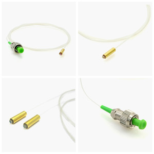
FC Fiber Optic Patch Cord

The FC has become the connector of choice for singlemode fibers and is mainly used in fiber optic instruments, SM fiber optic components, and in high speed fiber optic communication links. This high precision, ceramic ferrule connector is equipped with an anti rotation key, reducing fiber endface damage and rotational alignment sensitivity of the fiber. The key is also used for repeatable alignment of fibers in the optimal, minimal loss position. Multimode versions of this connector are also available.

The FC fiber optic patch cable is available in both singlemode and multimode versions, and is fully intermateable with NTT-FC products. Both smf and mmf versions FC fiber optic patch cord come with a zirconia ceramic ferrule with pre-polished PC profile and convex spherical end.

ST Fiber Optic Patch Cord

The ST connector is used extensively both in the field and in indoor fiber optic LAN applications. Its high precision, ceramic ferrule allows its use with both multimode and single9mode fibers. The bayonet style, keyed coupling mechanism featuring push and turn locking of the connector, prevents over tightening and damaging of the fiber end. The insertion loss of the ST connector is less than 0.5 dB, with typical values of 0.3 dB being routinely achieved.

ST fiber cable connector has a bayonet-style housing and a long spring-loaded ferrule hold the fiber. They are available in both multimode or singlemode versions. Horizontally mounted simplex and duplex adapters are available with metal or plastic housing, with a choice of phosphor bronze or zirconia split sleeve. The ST fiber patch cord is one of the older generations of connector, but is still widely used for multimode networks, including LANs for buildings and campuses.

LC Fiber Optic Patch Cord

The LC connector developed by Lucent Technologies is a more evolutionary approach to achieving the goals of a SFF connector. The LC connector utilizes the traditional components of a SC duplex connector having independent ceramic ferrules and housings with the overall size scaled down by one half. The LC family of connectors indcludes a stand-alone simplex design; a “behind the wall” (BTW) connector; and the duplex connector available in both single-mode and multimode tolerances, all designed using the RJ-style latch. The LC connectors ar available in both simplex and duplex configurations. They are available in industry standard beige and blue colors for multimode and single-mode applications, respectively. The connectors will accommodate 900 um buffered fiber and 1.60 mm (0.063-in) and 2.40-mm (0.094-in) jacketed cable.

LC patch cord is with LC fiber optic connector,which is a push and latch structure. LC connector has a small form-factor Fiber optic connector, is widely used for densely installation.The LC fiber optic connector has good performance and is highly favored for singlemode.The LC fiber patch cable connector is used on small diameter mini-cordage (1.6mm/2.0mm) as well as 3.0mm cable. LC fiber cable connectors are available in cable assembled or one piece connectors. The LC fiber optic assemblies family is Telcordia, ANSI/EIA/TIA and IEC compliant.

SC Fiber Optic Patch Cord

The SC connector is becoming increasingly popular in single9mode fiber optic telecom and analog CATV, field deployed links. The high precision, ceramic ferrule construction is optimal for aligning single9mode optical fibers. The connectors’ outer square profile combined with its push pull coupling mechanism, allow for greater connector packaging density in instruments and patch panels. The keyed outer body prevents rotational sensitivity and fiber endface damage. Multimode versions of this connector are also available. The typical insertion loss of the SC connector is around 0.3 dB.

SC fiber patch cord is one of the earliest stype and one of the most commonly used fiber optic cable, it is convenient to use and cost saving – It is the most cheapest type fiber optic cable. SC fiber patch is widely uesed in fiber optic networks. SC fiber patch cable is with zirconia sleeve and plastic housing.

MT-RJ Fiber Optic Patch Cord

mtrj connector

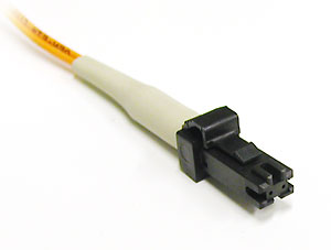
MT-RJ uses a form factor and latch similar to the 8P8C (RJ45) connectors. Two separate fibers are included in one unified connector. It is easier to terminate and install than ST or SC connectors. The smaller size allows twice the port density on a face plate than ST or SC connectors do. The MT-RJ connector was designed by AMP, but was later standardized as FOCIS 12 (Fiber Optic Connector Intermateability Standards) in EIA/TIA-604-12. There are two variations: pinned and no-pin. The pinned variety, which has two small stainless steel guide pins on the face of the connector, is used in patch panels to mate with the no-pin connectors on MT-RJ patch cords. The MT-RJ fiber connectors utilize precision molded MT ferrules pioneered by NTT, together with precision metal guide pins and precise housing dimensions to ensure fiber alignment when mating. The MT-RJ fiber patch cable is reliable and simple to terminate.

MU Fiber Optic Patch Cord

The MU connectors have a simple push-pull design and compact miniature body. The MU connector ferrules are half the size of the standard FC, SC connectors (1.25 mm ferrule O.D.) and are excellent for high density installations.JDS Uniphase MU connectors are available with 900 μm buffered fiber. These connectors achieve excellent insertion loss (0.1 dB typical 1 ) and provide high return loss (55 dB typical 1 ).

MU fiber patch cable has a push-pull style design. MU fiber patch cord is completely intermateable with NTT-MU products, The MU connector looks a miniature SC connector with a 1.25 mm ferrule. It is a popular patch cable type in Japan.