SMF or MMF, Which to Choose for Date Center Cabling?

It is critically important to choose the suitable cabling plant for data center connectivity, because the wrong decision may leave a data center incapable of supporting future grown, requiring an extremely costly optical cable plant upgrade to move to higher speeds. In the past, multimode fiber (MMF) has been widely deployed in data center for many years because of the high cost of single mode fiber (SMF). However, the price difference between SMF and MMF has been largely negated as technologies have evolved. With cost no longer the dominant decision criterion, operators can make architectural decisions based on performance. So SMF or MMF, which should be chosen for data center cabling? Keep reading and you’ll find the answer.

MMF – Unable to Reach the Distance Need

Many data center operators who deployed MMF OM1/OM2 fiber a few years ago are now realizing that these MMF cannot support higher transmit rates like 40 GbE and 100 GbE. So some MMF users have been forced to add later-generation OM3 and OM4 fiber to support standards-based 40GbE and 100GbE interfaces. But the physical limitations of MMF mean that the distance between connections must decrease when data traffic grows and interconnectivity speeds increase. Deploying more fibers in parallel to support more traffic is the only alternative. So the limitations of MMF have become more serious when it has been widely deployed for generations. The operators must weigh unexpected cabling costs against a network incapable of supporting new devices.

MMF

SMF – A Viable Alternative

Due to the cost of the pluggable optics required, previously organizations were reluctant to implement SMF inside the data center, especially compared to MMF. However, newer silicon technologies and manufacturing innovations are driving down the cost of SMF pluggable optics. Fiber optic transceivers with Fabry-Perot edge emitting lasers (single-mode) are now comparable in price than power dissipation to VCSEL (multimode) transceivers. Moreover, SMF eliminates network bandwidth constraints, where MMF cable plants introduce a capacity-reach tradeoff. This allows operators to take advantage of higher-bit-rate interfaces and wave division multiplexing (WDM) technology to increase by three orders of magnitude the amount of traffic that the fiber plant can support over longer distances. All these factors make SMF a more viable option for high-speed deployment in data center.

SMF

Comparison Between SMF and MMF

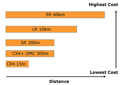
With 40 GbE and 100 GbE playing roles in some high-bandwidth applications, 10 GbE has become the predominant interconnectivity interface in large data centers. Put it simply, the necessity for fiber cabling supporting higher bit rates over extended distances is here today. With that in mind, the most significant difference between SMF and MMF is that SMF provides a higher spectral efficiency than MMF. It means that SMF supports more traffic over a single fiber using more channels at higher speeds. This is in stark contrast to MMF, where cabling support for higher bit rates is limited by its large core size. As a matter of fact, in most cases, currently deployed MMF cabling is unable to support higher speeds over the same distance as lower-speed signals.

Summary

The tradeoff between capacity and reach is important as operators consider their cabling options. Network operators need to assess the extend to which they believe their data centers are going to grow. For environments where users, applications, and corresponding workload are all increasing, SMF offers the best future proofing for performance and scalability. And because of fundamental changes in how transceivers are manufactured, those benefits can be attained at prices comparable to SMF’s lower performing alternative.

10GbE Interconnect Solutions Overview

New sophisticated networking services, coupled with the increase of Internet users push the Internet traffic to an even higher point, driving the need for increased bandwidth consequently. One Ethernet technology—10 Gigabit Ethernet (GbE) is adequate for such bandwidth demand, and has become widely available due to the competitive price and performance, as well as its simplified cabling structure.

Several cable and interconnect solutions are available for 10GbE, the choice of which depends on the maximum interconnect distance, power budget and heat consumption, signal latency, network reliability, component adaptability to future requirements, cost. Here cost includes more than what we call the equipment interface and cable cost, but more often the labor cost. Thus, choosing a 10GbE interconnect solution requires careful evaluation of each option against the specific applications. This text aims to introduce two main 10GbE interconnect solutions: fiber optics and copper.

Fiber Optics Solution

Fiber optic cables include single-mode fiber (SMF) and multi-mode fiber (MMF). MMF is larger in diameter than that of single-mode, thus portions of the light beam follow different paths as they bounce back and forth between the walls of the fiber, leading to the possible distorted signal when reach the other end of the cable. The amount of distortion increases with the length of the cable. The light beam follows a single path through thinner single-mode cable, so the amount of distortion is much lower.

fiber optics solution: SMF & MMF

The typical 10GBASE port type that uses MMF is 10GBASE-SR which uses 850nm lasers. When used with OM3 MMF, 10GBASE-SR can support 300m-connection distances, and when with OM4 MMF, 400m link length is possible through 10GBASE-SR SFP+ transceiver.

10GBASE-LR (eg. E10GSFPLR), 10GBASE-ER and 10GBASE-ZR are all specified to work via SMF. SMF can carry signals up to 80km, so it is more often used in wide-area networks. But since SMF requires a more expensive laser light source than MMF does, SMF is replaced by MMF when the required connection distance is not so long.

Copper Solution

10GBASE-CX4, SFP+ Direct Attach (DAC) and 10GBASE-T are all specified to operate through copper medium.

  • 10GBASE-CX4

Being the first 10GbE copper solution standardized by the IEEE as 802.3ak in 2002, 10GBase-CX4 uses four cables, each carrying 2.5gigabits of data. It is specified to work up to a distance of 15m. Although 10GBase-CX4 provides an extremely cost-effective method to connect equipment within that 15m-distance, its bulky weight and big size of the CX4 connector prohibited higher switch densities required for large scale deployment. Besides, large diameter cables are purchased in fixed lengths, causing problems in managing cable slack. What’s more, the space isn’t sufficient enough to handle these large cables.

  • SFP+ DAC

SFP+ Direct Attach Cable (DAC), or called 10GSFP+Cu, is a copper 10GBASE twin-axial cable, connected directly into an SFP+ housing. It comes in either an active or passive twin-axial cable assembly. This solution provides a low-cost and low energy-consuming interconnect with a flexible cabling length, typically 1 to 7m (passive versions) or up to 15m (active versions) in length. Below is the SFP+ to SFP+ passive copper cable assembly with 1m length, 487655-B21, a HP compatible 10GbE cabling product.

SFP+ to SFP+ passive copper cable assembly, 1m link length

  • 10GBASE-T

10GBASE-T, known as IEEE 802.3an-2006, utilizes twisted pair cables and RJ-45 connectors over distances up to 100m. Cat 6 and Cat 6a are recommended, with the former reaching the full length at 100m, and the latter at 55m. In a word, 10GBASE-T permits operations over 4-connector structured 4-pair twisted-pair copper cabling for all supported distances within 100m. Besides, 10GBASE-T cabling solution is backward-compatible with 1000BASE-T switch infrastructures, keeping costs down while offering an easy migration path from 1GbE to 10GbE.

Conclusion

In summary, two main media options are available for 10GbE interconnect: copper and fiber optics, including 10GBASE-CX4, SFP+ DAC, 10GBASE-T, 10GBASE-SR, 10GBASE-LR, 10GBASE-ER, 10GBASE-ZR, and so on. Fiberstore offers all these 10GBASE SFP+ modules and cables for your 10GbE deployment, which are quality-assured and cost-effective, like E10GSFPLR and 487655-B21 mentioned above. For more information about 10GbE interconnect solutions, you can visit Fiberstore.

Cabling Data Center Process: Planning & Implementing its Infrastructure

Today’s data centers are the home to diverse bandwidth-demanding devices, like servers, storage systems, and backup devices which are interconnected by networking equipment. All these devices drive the need for reliable and manageable cabling infrastructure with higher performance and more flexibility for today and future growth. While managing the cabling in data centers, two main processes are included: planning the cabling infrastructure and implementing the cables.

Planning the Cabling Infrastructure

As networking equipment becomes denser, and port counts in data centers increase to several hundred ports, managing cables connected to these devices becomes a difficult challenge. Thus, during planning the cabling infrastructure, it’s wise to do the following:

Choosing Fiber Cable Assembly

This assembly has a single connector at one end of the cable and multiple duplex breakout cables at the other end, an alternative to avoid cable management. The LC (Lucent Connector) -MPO (Multifiber Push-On) breakout cable assemblies are designed to do just that. The idea is to pre-connect the high-density, high- port-count LC equipment with LC-MPO breakout cable to dedicated MPO modules within a dedicated patch panel, reducing equipment cabling clutter and improving cable management. This image below show the LC-MPO breakout cable assembly that consolidates six duplex LC ports into one MPO connection.

breakout

Nowadays, this breakout technology is widely used in 40 Gigabit Ethernet (GbE) applications. Like QSFP-4X10G-AOC10M, this product is the QSFP to four SFP+ active optical breakout cable assembly with the 10m short reach.

Using Color to Identify Cables

Color coding simplifies management and can save you hours when you need to trace cables. Cables are available in many colors (table shown below). For instance, multi-mode fiber (MMF) looks in orange (OM1, OM2) and in aqua (OM3), while yellow is usually the color of single-mode fiber (SMF) which is taken as the transmission media when the required distance is as long as 2km, or 10km . Take WSP-Q40GLR4L for example, this 40GBASE-LR4L QSFP+ transceiver works through SMF for 2km link length.

Color coding

Implementing the Cabling Infrastructure

While implementing the cables, the following tasks should be obeyed by.

Testing the Links

Testing cables throughout the installation stage is imperative. Any cables that are relocated or terminated after testing should be retested. Although testing is usually carried out by an authorized cabling implementer, you should obtain a test report for each cable installed as part of the implementation task.

Building a Common Framework for the Racks

This step is to stage a layout that can be mirrored across all racks in data centers for consistency, management, and convenience. Starting with an empty 4-post rack or two, build out and establish an internal standard for placing patch panels, horizontal cable managers, vertical cable managers, and any other devices that are planned for placement into racks or a group of racks. The INTENTION is to fully cable up the common components while monitoring the cooling, power, equipment access, and growth for the main components in the racks.

A good layout discourages cabling in between racks due to lack of available data ports or power supply ports, allowing more power outlets and network ports than you need. This will save you money in the long run as rack density increases, calling for more power and network connectivity. Using correct length cables, route patch cables up or down through horizontal patch panels alleviates overlapping other ports. Some cable slack may be needed to enable easy removal of racked equipment.

Documentation

Typically, the most critical task in cable management is to document the complete infrastructure: including diagrams, cable types, patching information, and cable counts. It’s advised update the documentation and keep it accessible to data center staff on a share drive or intranet Web site.

Stocking Spare Cables

It’s suggestible to maintain an approximately the same amount on the installed cabling and ports in use, so as to face the environment variation or emergency.

Conclusion

Understanding the above-mentioned information about cabling planning and implementation helps you to have a scalable, dependable and manageable cabling infrastructure in data centers. Fiberstore offers many cable management tools, including fiber termination box, cable ties, and distribution cabinet. For more information about cable management solutions, you can visit Fiberstore.

The Evolution of 10GbE Cabling Technologies

Since Ethernet technology is born in 1970s, it has evolved continuously to meet the never-ceasing demands of even faster rates of data transmission, such as 10 Gigabit Ethernet (GbE). Along with this ongoing evolution, the cabling technologies that support the 10GbE applications have also advanced, so as to provide greater bandwidth to transmit data with reasonable cost and decreased complexity. Maybe you have few insights in this evolution. Don’t worry. This text mainly talks about the evolution of 10GbE cabling technologies, including fiber and copper cabling technologies.

The Institute of Electrical and Electronics Engineers (IEEE) 802.3 working group has published several standards regarding 10GbE, including 802.3ae-2002 (fiber -SR, -LR, -ER), 802.3ak-2004 (CX4 copper twin-ax InfiniBand type cable), etc. Actually, the evolution of cabling technologies have walked in step with that of 10GbE standards, especially associated with the difference between IEEE802.3ae and IEEE802.3ak standards.

IEEE802.3ae

Ratified in June 2002, the IEEE802.3ae standard outlined the following port types.

10GBASE-SR—It supports 10GbE transmission over standard multi-mode fiber (MMF) with distances of 33m on OM1 and 86m on OM2. Using 2000 MHz/km MMF (OM3), up to 300-m link lengths are possible. Using 4700 MHz/km MMF (OM4), up to 400 meter link lengths are possible. Like SFP-10G-SR-S (shown below), this Cisco 10GBASE-SR module listed in Fiberstore is able to support up to 300m using OM3 at the maximum data rate of 10.3125Gbps. In addition, SR is the lowest-cost optics (850nm) of all defined 10GbE optics.

SFP-10G-SR-S, supporting 300m link length using OM3

10GBASE-LR—This port type uses higher cost optics (1310nm) than SR and requires more complex alignment of the optics to support 10km link length over single-mode fiber (SMF).

10GBASE-ER—It’s a port type for SMF and uses the most expensive optics (1550nm) lasers, enabling a reach of 40km over engineered links and 30km over standard links.

IEEE802.3ak

Approved in February 2004, this IEEE802.3ak standard only defined 10GBASE-CX4—the first 10GbE copper cabling standard.

10GBASE-CX4—It’s a low-cost 10GbE solution intended for copper cabling with short-distance connectivity. Its affordability and wide availability makes 10GBASE-CX4 ideal for wiring closet and data center connectivity.

The CX4 standard transmits 10GbE over four channels using twin-axial cables which originated from Infiniband connectors and cable. The CX4 standard committee defined that the cables should be tighter in electrical specifications. Therefore, CX4 standard is not appropriate when longer length (>10 Infiniband cable is required. And It’s recommended to use only cables that are designed to meet IEEE 802.3ak specifications.

Another aspect of the CX4 cable is the rigidity and thickness of the cable. The longer the length used, the thicker the cable is. CX4 cables must also be factory-terminated to meet defined specifications.

After comparison between IEEE802.3ae and IEEE802.3ak standards, here goes a picture about the cabling cost and distance considerations.

 cabling cost and distance considerations

Besides IEEE802.3ae and IEEE802.3ak standards, there also exists IEEE802.3an standard. Proposed in November 2002, IEEE802.3an defined 10GBASE-T using unshielded twisted-pair (UTP) style cabling. The goal of this copper standard is to improve the performance and distance of copper cabling at a cost that is lower or similar to fiber.

From the above introduction, the evolution of cabling technologies is associated with the evolution of 10GbE standards. As 10GbE deployment becomes a commonplace, it’s of great importance to make wise cabling strategies.

Conclusion

Spurred by the demand for faster application speeds, cabling technologies evolved to support the 10GbE standards, thus to better accommodate bandwidth-intensive applications and traffic types. With 10GbE technology being pervasive, it’s necessary to understand the the different 10GbE standards and cabling technologies (mentioned above). Fiberstore supplies 10GbE application solutions, transceivers, copper and fiber cables all included, like AFBR-703SDZ-IN2, a 10GBASE-SR SFP+ transceiver. For more information about 10GbE system solutions, you can visit Fiberstore.

Fiber Optic Cable Handling Rules

Contaminated fiber optic cables can often lead to degraded network performance or even failure of the whole system. As such, to ensure that fiber optic cables can yield the best possible results of network performance, and it’s of great significance for network engineers to keep in mind how to handle fiber optic cables. Do you have any ideas? This text gives the guide to fiber optic cable handling rues.

Fiber Optic Cable Elements

Before delving into how to handle fiber optic cables, introduction to their makeup elements is required.

fiber optic cable fiver elements

Fiber optic cable generally consists of fiver elements (figure shown above): the optic core, optic cladding, a buffer material, a strength material and the outer jacket. Commonly made from doped silica (glass), the optic core is the light-carrying element at the center of the cable. Surrounding the core is the optic cladding, whose combination with the core makes the principle of total internal reflection possible. Surrounding the cladding is a buffer material used to help shield the core and cladding from damage. A strength material surrounds the buffer, preventing stretch problems when the fiber cable is being pulled. The outer jacket is added to protect against abrasion, solvents, and other contaminants.

The outer jacket on fiber optic patch cord is often color-coded to indicate the fiber types being used. For instance, multi-mode fiber (MMF) is usually in orange to distinguish from the color yellow for single-mode fiber (SMF) through which fiber optic transceivers realize relatively long distance, such as MGBLX1. This Cisco 1000BASE-LX SFP transceiver is able to achieve 10km link length over SMF.

Cisco 1000BASE-LX SFP, SMF

Fiber Optic Cable Handling Rules

Despite its outer protection mentioned above, fiber optic cable is still prone to damage. In such as case, a series of fiber cable handing rules are made to ensure that a cable is handled properly, so as to maintain the optimized performance, minimum insertion loss and safe working environments.

Rule 1: The exposed fiber end from coming in contact with all surfaces should be protected. If you contact the fiber with hard surfaces, then the end of it shall be scratched or chipped, causing the degraded performance.

Rule 2: It’s highly recommenced to lean the connector (plug) end each time it is inserted into an adapter, since since a dirty connector will contaminate an adapter.

Rule 3: If a fiber needs to be pulled, use the connector strain relief. Directly pulling on the fiber may result in the glass breaking.

Rule 4: It’s ill-advised to use your hands to clean a fiber work area. If you use your hands to wipe clean a work area, a piece of glass may get lodged into your hands. Considering the size of the glass, this glass may not be visible to the naked eye, bringing about eye damage.

Rule 5: If possible, always keep a protective cap on unplugged fiber connectors, because covering the adapters and connectors will help to avoid contamination and collection of residue. Besides, store unused protective caps in a resealable container in order to prevent the possibility of the transfer of dust to the fiber. Locate the containers near the connectors for easy access.

dust cap covers for protection

Rule 6: It’s suggestible to use fiber-cleaning materials only once. If optic grade wipes are used to clean the fiber end, they should be discarded immediately after the fiber surface has been wiped to avoid contamination.

Rule 7: The minimum bend radius of the fiber optic cable must be maintained. Surpassing the bend radius may cause the glass to fracture inside the fiber optic cable. Equally, to cause a twist of the cable is also not proposed.

Rule 8: Never look into a fiber while the system lasers are on. Eye damage may occur if you stare directly at a fiber end which is working. Always make sure that the fiber optic cables are disconnected from the laser source, prior to inspection.

After discussion, these handling rules may help you to deal with fiber optic cables and improve your network performance.

Conclusion

Proper handling procedures for fiber optic cables are needed to eliminate the possibility of being contaminated or damaged, and provide a clean environment for the network system. Fiberstore supplies many different types of fiber optic cables with high quality for various applications, like MTP cable. You can visit Fiberstore for more information about fiber optic cables.

40G Needed for Data Center Networks

Driven by growing bandwidth and network performance demand, data center network infrastructure is witnessing a transformation. As technology evolves, standards are completed to define data rates such as 40 Gigabit Ethernet (GbE) to meet such demands of high networking speed and performance. 40GbE addresses physical layer specifications for communication across backplanes, copper cabling, single-mode fiber(SMF), and multi-mode fiber (MMF).

The Need for Higher Speed – 40G

1G and 10G data rates are not adequate to meet the future needs of high-bandwidth applications. The requirement for higher data rates is being driven by many factors. Switching and routing, virtualization, convergence and high-performance computing environments are examples of where these higher network speeds will be required within the data center environment. Additionally, Internet exchanges and service provider peering points and high-bandwidth applications, such as video-on-demand driving the need for a migration from 10G to 40G interfaces.

40G Physical Layer Alternatives

40GbE standards already exist for SMF, MPO based MMF, as well as copper cables. Listed below are three physical layer solutions for 40GbE.

Single-mode Fiber

Due to its long reach and superior transmission performance, SMF is specified for carrying 40Gbps data up to a distance as long as 10km (40GBASE-LR4). The physical layer electronics and optics consist of four channels, each carrying 10Gbps data with different wavelengths. When there is no need to consider budget or the link distances are long, SMF is the preferred option for 40GbE in data center networks.

Multi-mode Fiber

MMF with parallel optics MPO interface is the most popular medium for 40GbE today (40GBASE-SR4). Take F5-UPG-QSFP+ for example, Fiberstore compatible F5 Networks F5-UPG-QSFP+ (figure shown below) is a 40GBASE-SR4 QSFP+ transceiver with MPO connectors. It supports link lengths of 100m and 150m, respectively, on OM3 and OM4 MMFs at a wavelength of 850nm in a data center network. (OM3 and OM4 fibers were selected as the only MMFs for 40G consideration.)

Copper Twinax

For short reach channels up to a length of 7m, 40GBASE-CR4 standard specifies use of twinax copper cable assembly. One typical application of this kind of copper cable is in 40G QSFP+ direct attach cable (DAC). For instance, Fiberstore compatible Brocade 40G-QSFP-C-0101 is the QSFP+ to QSFP+ passive copper cable assembly for very short distances.

40G Transceivers

40G transceivers were developed along several standard form factors. The C Form-Factor Pluggable (CFP) transceiver features 12 transmit and 12 receive 10-Gbps lanes to support one 100 Gigabit Ethernet port, or up to three 40 Gigabit Ethernet ports. Its larger size is suitable for the needs of single-mode optics and can easily serve multi-mode optics or copper as well. The CXP transceiver form factor also provides 12 lanes in each direction, but is much smaller than the CFP and serves the needs of multi-mode optics and copper. The Quad Small-Form-Factor Pluggable (QSFP) is similar in size to the CXP and provides four transmit and four receive lanes to support 40 Gigabit Ethernet applications
for multi-mode fiber and copper today.

Conclusion

40GbE supports high-speed switching, routing, and application functions in data centers. It provides optimized performance in meeting data center requirements. As a professional fiber optic products supplier and manufacturer, Fiberstore offers various 40GbE products, like 40G transceivers, and 40G cabling available both in fiber and copper. You can visit Fiberstore for more information about 40GbE solutions.