What Is an Internet Switch and How Does It Work?

The Internet switch, since its birth, has been growing rapidly not only in function but also in performance. Experts have researched and developed generations of Internet switches, while the majority of people may be new to the devices, not taking fully advantage of them. This paper aims to help you get further understanding of Internet switch definition, benefits and working principle.

What Is an Internet Switch?

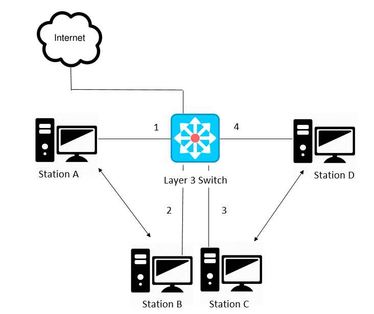
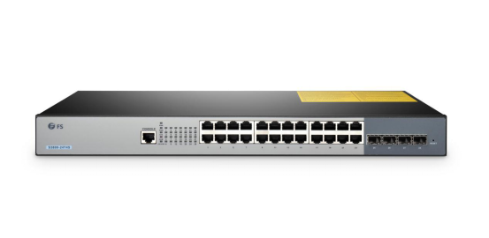
An Internet switch is another name of network switch. It is a critical component in many business networks, for the fact that they connect various PCs, printers, assess points, phones, lights, servers and other hardware. With an Internet switch, users can send and receive information and approach shared resources in a smooth, highly secure, and transparent manner. It addresses the low speed which was previously the shortcoming of hub, to sustain an efficient and high-speed information exchanging among hosts.

Internet switch

Why Use an Internet Switch?

  • Add More Ports to Your Router

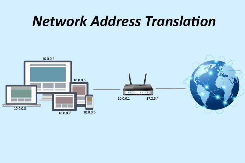
In household use, many families view router as a must and Internet switch as an alternative. The fact is that the ports left for use is few when the router is connected and working. Given this, some will turn to an entry-level switch to add more Ethernet ports to the network. This kind of switch is usually the unmanaged switch that has no settings or special features itself. Your router continues to handle your Internet connection, letting your devices talk to one another and restricting what certain devices can do through parental controls or other settings—the switch is effectively invisible.

  • Add Ethernet All over Your House

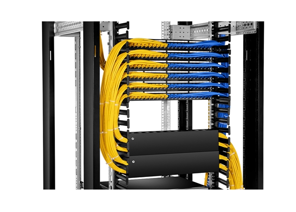
Though the Wi-Fi is prevalent and convenient, you still need wired Ethernet if you want to play online games, stream 4K video or transfer large files over your network frequently. That can be guaranteed by a gigabit Ethernet switch to give you high speed and smooth network accessing.

  • Use Wires to Improve Wi-Fi

It is known to all that Wi-Fi can be freely accessed by anyone who has the password. However, as the users increase, the network may lag and be congested. Here you can install an Internet switch to improve your Wi-Fi performance by reducing the number of devices competing for wireless bandwidth. Faster switches like 10gbe switch, 40gbe switch and 100gbe switch will be recommended here.

How Does an Internet Switch Work?

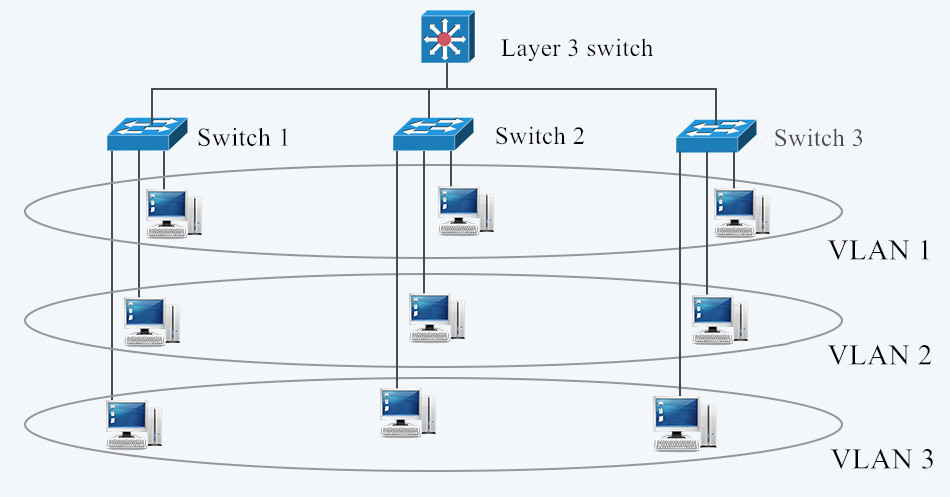
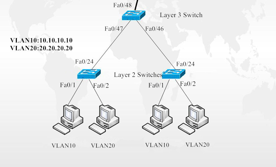
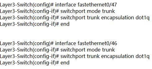
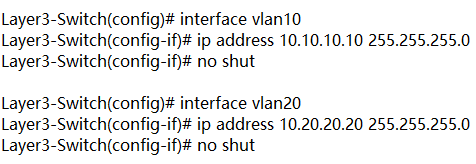
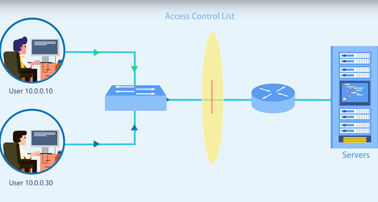
As the name suggests, an Internet switch is a device to switch information in the local area network. But how? It is the intriguing part of the Internet switch. Well, a network switch determines where to send each incoming message by looking at the physical device address (also known as the Media Access Control address or MAC address). Inside the switch there is a table that match each MAC address to the port from which the MAC address has been received. If a frame is to be forwarded to a MAC address that is unknown to the switch infrastructure, it is flooded to all ports in the switching domain. Broadcast and multicast frames are also flooded. Otherwise, it goes to the specific port.

Conclusion

Having read this article, you are expected to have a generally understanding of the Internet switch. Internet switch steps into people’s life, bringing great benefits and convenience. Undoubtedly, it is a breakthrough in network technology. If you determines to get it, give full play to its role to better serve you applications.

Related article: Core Switch Vs Distribution Switch Vs Access Switch

How to Configure Inter VLAN Routing on Layer 3 Switches?

With the development of technology, no matter how far you are away from families, you can communicate with them at any time in any places. The same is true to the optic communication, regardless of the physical locations of two hosts or the different VLANs they belong to, they can exchange with each other by inter VLAN routing. Then what is inter VLAN routing and how to configure inter VLAN routing on layer 3 switches?

What Is Inter VLAN Routing?

In figure 1, three computers connected to a gigabit Ethernet switch form a LAN (local area network) within a limited area. However, they cannot communicate with hosts in another LAN, because there is no connection between these Ethernet switches. Then there comes the VLAN which provides us with logical separation or segmentation of our networks to facilitate communication among hosts in different LANs. However, each VLAN is a unique broadcast domain, so computers on separate VLANs are unable to communicate with each other by default. There is a way to solve the problem, and that’s what we are going to shed light on—inter VLAN routing.

LAN and VLAN in NetworkingFig. 1 LAN and VLAN in Networking

The process of forwarding network traffic from one VLAN to another VLAN using routing is known as inter-VLAN routing. One of the ways to carry out inter-VLAN routing is by connecting a router to the switch infrastructure. When using a router to facilitate inter-VLAN routing, the router interfaces can be connected to separate VLANs. Devices on those VLANs communicate with each other via the router. Apart from that, a more convenient way is introduced—configure inter VLAN routing on layer 3 switches. Layer 3 switching is more scalable than a router which only provides a limited number of available ports.

How to Configure Inter VLAN Routing on Layer 3 Switches?

To enable a layer 3 switch to perform routing functions, the switch must have IP routing enabled. 10gb Ethernet switch and 40gb Ethernet switch are recommended for working as layer 3 switch.

Inter VLAN Routing

Fig.2 Inter VLAN Routing on Layer 3 Switches

In figure 2, layer 3 switch is configured with IP address 10.0.0.1. VLAN10 and VLAN20, with IP address 10.10.10.10 and IP address 10.20.20.20 respectively are configured on layer 2 switches. These two IP addresses will be the default gateway addresses for hosts belonging to VLAN10 and VLAN20 on the layer 2 switches respectively. Also, all interfaces connecting the three switches must be configured as trunk ports to allow VLAN10 and VLAN20 tagged frames to pass between switches. Traffic between VLAN10 and VLAN20 will be routed by the layer 3 switch after configuring inter VLAN routing. These steps can be achieved by VLAN configuration command below.

Create VLANs 10 and 20 in the switch database

inter VLAN routing configuration 1
Assign port Fe0/1 in VLAN 10 and port Fe0/2 in VLAN 20

inter VLAN routing configuration 2

Create trunk port Fe0/24

inter VLAN routing configuration 3

Enable layer 3 routing and create VLANs 10 and 20 in the switch database

inter VLAN routing configuration 4

Create trunk ports Fe0/47 Fe0/46

inter VLAN routing configuration 5

Configure Switch VLAN Interfaces (SVI) to acts as a virtual layer 3 interface on the layer 3 switch

inter VLAN routing configuration 6

Conclusion

VLAN is created to enable the communication among hosts in different LANs. Inter VLAN routing is developed to realize the exchange among hosts in different VLANs. Inter VLAN routing on layer 3 switch without a router is also approachable with the development of technology. For more configuration about network switches, please refer to our website www.fs.com.

Can a Layer 3 Switch Be Used as a Router?

With the development of technology, network switch grows not only in speed like the migration from gigabit Ethernet switch, to 10gb switch, 40gb switch and 100gb switch, but also in complexity to acquire more functions and meet complicated conditions. Layer 3 switch is equipped with advanced functions and is sometimes compared with a router by people. What are layer 3 switch and router? Can a layer 3 switch act as a router? This post will focus on this problem.

What Is Layer 3 Switch and How It Works?

The data switch is a layer 2 switching device that dynamically transmits packets according to the physical addresses (MAC addresses) of connected devices. Layer 3 switch, on the basis of the data switch, boasts additional routing decisions by inspecting the IP addresses. Layer 3 switches are thus able to segregate ports into separate virtual LANs (VLANs) and perform the routing between them. Additionally, this switch helps reduce the amount of broadcast traffic, simplify security management, and improve fault isolation.

layer 3 switch in networking

What Is Router and How It Works?

A router works at layer 3 of the OSI Model (Network). It is a device usually located at gateways where networks meet, to connect various local networks and wide networks. It decides where to send packets by utilizing an IP Routing table. When an IP packet comes in, the router looks up the destination IP in the IP Routing table. If that destination IP is not found in the table, the router will drop the packet.
The router can perform NAT to translate the private IP address to public address, which can get you into the Internet. So it is a common network device in household use.

Can a Layer 3 Switch Be Used as a Router?

As a layer 3 switch possesses the routing function of a router, can we replace a router with it? Let’ s have a detailed view of their similarities and disparities.

Layer 3 Switch Vs Router

Layer 3 Switch Vs Router: Similarity

Both layer 3 switch and router work at layer 3 of the network. Layer 3 switches technically have a lot in common with traditional routers. Both of them can support the same routing protocols, inspect incoming packets and make dynamic routing decisions based on the source and destination addresses inside. The switches can also be configured to support routing protocols such as RIP, OSPF, and EIGRP.

Layer 3 Switch Vs Router: Disparity

Internally, the hardware inside a layer 3 switch blends that of traditional switches and routers. As for packet forwarding, router transmits packet by a microprocessor-based software routing engine, while the switch performs switching through hardware. After routing the first data flow, the layer 3 switch will generate a mapping table of MAC addresses and IP addresses, so that the same data flow will directly pass through the layer 2 according to this table, thus eliminating network delay and improving the efficiency of packet forwarding. Externally, layer 3 switches do not offer the WAN-type ports as standard routers do, so they lack WAN functionality.

Router requires configurations before deployment due to the inbuilt operating system. On the contrary, the layer 3 switch is usually ready to go when acquired, and configurations are optional as you like.

From a software perspective, layer 3 switches are not capable of the extra services that routers typically provide, such as NAT and NetFlow.

Conclusion

All in all, it is not recommended to replace a router with layer 3 switch, but you can apply them in the same network at the same time. In addition, whether a layer 3 switch can supplant a router relies upon the switch model and what you expect from it. Some layer 3 switches are almost router substitutions, with a full scope of WAN, firewall, VoIP, and so on. However, those switches are costly, and most layer 3 switches just have Ethernet ports. In this way, a dedicated router is cost-effective than a layer 3 switch.

Bend Radius—How It Can Impact Your Cable Performance?

Why should fiber optic cable not be tightly bent? Are fiber optic cable fragile? These issues are what users care about when deploying fiber patch cables. Usually, fiber optic cable is made from two bend sensitive materials: plastic or glass. It is broken easily when kinked or bent too tightly to exceed the minimum bend radius of cable. Then which factor will influence bend radius? How to choose cables according to it? This blog will provide some hints.

Why Bend Radius Is Important?

When you deploy the fiber optic cable, it is inevitable to flex, pull and bend it due to the practical conditions. However, it is the bend radius that determines how much you can bend a cable. It represents as the safe value that can prevent your cable from damaging or degrading its performance. If a cable is bent beyond its allowed radius, it will generate crosstalk or interference in data transmission, or even shorten its life. That’s why it’s important to know the bend radius of the cables, especially the minimum bend radius,which is the smallest allowed radius the cable can be bent around without signal loss or impairment.

bend radius of cable

Factors Impact Bend Radius of Cable

The bend radius may differ from cables. The fact is the smaller the minimum bend radius, the more flexible the cable. Here list some factors that may affect this radius of cable.

  • Outer Jacket Thickness

The thickness of the outer jacket of a fiber patch cable intended for bending will influence the potential minimum curve radius. Generally speaking, if the outer jacket is thick, the fiber patch cable will have a smaller bend radius. This can be translated by the fact that when the cable is bent, the stretching force makes the outer jacket thinner and even broken. Therefore, if the outer jacket is thin itself, the external tension may deform of break the fragile cable.

  • Material Ductility

Cables are manufactured by different materials, and this will affect the radius of the bend. Ductility refers to the flexibility of material under tensile stress or stretching force. If you would like to obtain small curve radius, you should choose cables made of highly ductile materials like copper. An alternative such as glass is more brittle than flexible.

  • Core Diameter

The large core diameter determines the small bend radius. Simply put, the single mode fiber has a smaller diameter than multimode fiber, and the single mode fiber cable bears less weight or bending than multimode fiber cable. That’s why the bending radius of single mode fiber optic cable is larger than the multimode fiber optic cable.

How to Choose Fiber Optic Cables based on Bend Radius?

Generally, the multimode fiber optic cable is recommended if the bend radius is the only consideration. And another option is BIF fiber cable. BIF means the bend insensitive fiber which enables tight curve radius when cables are bent or twisted. FS adopts it in producing both multimode and single mode fiber cables to endow them much smaller bend radii than ever before. It realizes more convenience in cable management, as well as less signal loss and less cable damaging. Here is a bend radius chart of BIF fiber optic cable.

Fiber Cable Type
Minimum Bend Radius
OM3/OM4 MTP BIF
7.5mm
Single Mode OS2 MTP BIF
10mm
Uniboot OS2 LC BIF
10mm
Uniboot OM3/OM4 LC BIF
7.5mm

Conclusion

To sum up, the bend radius of cables is paramount for fiber patch cable installations. Factors which influence the minimum radius of fiber optic cable include the outer jacket thickness, material ductility and core diameter. To protect the integrity and performance of cable, we shall not bend the cable beyond its allowed radius.

Connect Optical Transceivers of Different Brands, Fibers or Wavelengths?

Optical transceivers usually work coordinately on a pair of network switches. As switch is responsible for directing the flow of data, optical transceiver works for transforming light to data or the opposite. Then how do two transceiver modules work with each other? Can I connect two optical transceivers of different brands, fiber types or wavelengths? You can find answers here.

How Do Two Optical Transceiver Talk to Each Other?

It is known to all that the fiber optic transceiver contains a transmitter and a receiver in the same component. These are arranged in parallel so that they can operate independently from each other. When working on two switches in the same network, the transmitter on one optical transceiver takes an electrical input and converts it to an optical output from a laser diode or LED. The light from the transmitter is coupled into the fiber with a connector and is transmitted through the fiber optic cable plant. The light from the end of the fiber is coupled to a receiver on the other transceiver where a detector converts the light into an electrical signal which is then conditioned properly for use by the receiving equipment.

How optical transceiver works

Fig1. How optical transceiver works

Can I Connect Two Optical Transceivers of Different Brands, Fibers or Wavelengths?

When people are under-budgeted or in urgent need of original optical transceivers that are out of stock, they may turn to other or third-party transceivers. But how to make different transceivers work coordinately without link failure? Is it possible to connect two optical transceivers of different brands, fibers or wavelengths?

Optical Transceiver of Different Brands

As is known to all, fiber optic transceivers are manufactured with a lot of standards and protocols. If the SFP types are of the same protocol at each end, for example: both sides with SX, LX or whatever is currently in use, you can build the link between them. Please note that only the identical protocol is far more enough.

If the network switch comes from different vendors and optical transceivers with different protocols, you will get a dead link between network switch and the transceiver, thus the whole network fails. Make sure the transceiver and the switch at both ends are compatible with each other. However, as the transceiver compatibility is introduced to the optic field, many optical transceivers are now produced to be compatible with other brands. FS almost has no transceiver compatibility issues with other brand switches as all the optical transceivers have been tested to ensure its compatibility before shipping.

Optical Transceiver with Different Fiber Types

Common sense says a multimode sfp cannot work well with a single mode sfp, as the single mode fiber features a narrow core, allowing only a single mode of light to propagate while the multimode fiber has a wider core enabling multiple modes of light to propagate.

Well, as the network evolves, it is unavoidable to use single mode devices on the existing multimode fiber cables, which forces the birth of the mode conditioning cable used for single mode to multimode conversion. It is generally a duplex multimode cable that has a small length of single mode fiber at the start of the transmission length. As for optical transceiver with single mode fiber, connect the single mode connector of the cable into the transmit bore of the transceiver, and multimode connectors of the cable into the receive bore of the transceiver with all other connections going as normal.

Optical transceiver works with mode conditioning cable

Fig.2 Optical transceiver works with mode conditioning cable

Optical Transceiver on Different Wavelengths

A given transceiver generally supports a specific wavelength for both transmitting and receiving. It is vital the wavelength of the fiber optic transceivers (850nm, 1310nm, 1550nm) matches on each end, as a 1310nm sfp transceiver will not talk to a 850nm sfp transceiver. Data transmission implies that data is sent from one end to the other. The SFP transceiver on one end converts electrical signals into optical signals. A built-in laser transmits light through the fiber to the other side. Here, an optical diode converts the light back into an electrical signal. To guarantee that the SFP at the other end is capable of doing this, the SFPs at both ends should support the same wavelength.

Different wavelengths of optical transceiver
Fig.3 Different wavelengths of optical transceiver

Conclusion

To make sure your optical transceivers work smoothly with each other, be careful about their protocols, wavelengths and fiber types in case of link failure. FS provides a great range of fiber optic transceivers with no transceiver compatibility problem and transceiver prices are very competitive.

What Is ACL (Access Control List) and How to Configure It?

Though the robust network promotes the connectivity among people at every comer of the globe, we may not enjoy its convenience or gain the information we want as easily and casually as it thought to be. Due to the access control list, some paths to a certain server may have been blocked manually. Well, what is access control list? Why does it get in my way to the fantastic world?

What Is ACL (Access Control List)?

ACL stands for Access Control List. It is a list of a series of rules that are specified to permit or deny traffic flow. More precisely, ACL serves to filter data packet based on a given filtering criteria on a router or data switch interface, thereby controlling access to your network or to specific files or folders on your network. How does ACL work? As we all know, when a router receives a packet, it will routinely identify its destination address and find an entry in routing table that can match with it. If succeed, the packet can be forwarded, otherwise, discarded. We can run ACL conditions before or after the router makes forward decision. If deny condition matches, drop the packet immediately, otherwise, move on to the next step as normal.

access control list

There are mainly two types of ACL, namely standard ACL and extended ACL. The former one only specifies the source address while the latter can permit or deny traffic based on both the source and destination addresses as well as the ports (for TCP or UDP), or the IPCMP type (for ICMP).

Why Do We Need Access Control List?

First, it works as a security for your network by filtering the unwanted traffic and blocking specific hosts. In the above scenario, if we exclude the ACL, anyone who knows the right destination address can send his packet through the router with no security policy, and damage may ensue. Given this, you can customize ACL conditions to decide who has access to resources in the network.

Besides, ACLs are used for several other purposes such as prioritizing traffic for QoS (Quality of Services), triggering alert, restricting remote access, debugging and so on.

How to Configure Access Control List?

We’ve produced a video for your better understanding of ACL network and ACL configuration. FS S5800/S5850/S8050 series switches are used in this video. Here are the basic access control list commands.

access contro list 1

This step helps enter the global configuration mode

access contro list 2

In this step, we create an ACL, and its number is “123”. Then we can add rules to the ACL. Please note that ACL number for the standard ACLs has to be between 1—99 and 1300—1999, and extended access list numbers ranges from 100 to 199, and from 2000 to 2699.

access contro list 3

Use the host keyword to specify the host you want to permit or deny. This means that deny tcp host 192.168.1.2 access to 192.168.1.1.

access contro list 4

The command above permits all message.

access contro list 5

Here create a class-map and name it “http”.

access contro list 6

Match the access control list of “123”.

access contro list 7

Create policy-map “web”.

access contro list 8

Associate the class-map “http” with the policy-map.

access contro list 9

Enter the eth-0-1 port on FS S5850-32S2Q 10gbe switch.

access contro list 10

Invoke the policy table “web” in the inbound direction of the interface.

The series of operations ban successfully the address 192.168.1.1 from entering the switch now.

Conclusion

Having read this article, you may get acquainted with access control list and know how to configure it. The ACL network helps prevent others from entering into your private network space while keeping you out from where others don’t let you in. Everyone can adopt it to manage your own networking condition. In this way, FS provides you with good quality equipment like fiber switch and PoE network switch and best solutions.

NAT: Why Do We Need It?

NAT, which is critical to the IPv4 networks we still use today, has been hotly debated as the IPv6 grows with more addresses. However, since the IPv6 is not full-fledged, the existence of NAT still makes sense. Here I will introduce NAT definition and figure how NAT works and why we need it.

What Is NAT?

NAT, known as network address translation, is the method adopted by a firewall or router to assign the public addresses to the devices work in the a private network.

It translates the private IPv4 addresses we use in our internal networks into public IPv4 addresses that can be routed over the internet. As we all know, the private addresses may be occupied by connected local service—computers, game consoles, phones, fiber switches etc. to communicate with the modem/router and other devices on the same network. However, the home network connection uses a single public IP address to access the internet. Given this, NAT is responsible for translating the IP address of every device connected to a router into a public IP address at the gateway. Then those devices can connect to the internet.

NAT(network address translation)

NAT: Why We Need?

Assume that you have 3 PCs, a gigabit Ethernet switch which connects 6 PCs, a 10 gigabit switch connecting 6PCs and one smart phone, two ipads and all of them need to work at the same time, then you need to get each of them an IP address accessible to the Internet. But due to a lack of IPv4 IP address space, it is hard to handle the massive number of devices we use every day. Well, the network address translation, proposed in 1994, has become a popular and necessary tool in the face of IPv4 address exhaustion by representing all internal devices as a whole with a same public address available. Together with its extension named port address translation, the network address translation can conserve IP addresses.

Safety, another issue we may concern when accessing the external internet, can partly be addressed by network address translation which servers as a strict controller of accessing to resources on both sides on the firewall. The hackers from outside cannot directly attack the internal network while the internal information cannot access the outside world casually.

How Does NAT Work

A router carrying NAT consists of pairs of local IP addresses and globally unique addresses, by translating the local IP addresses to global address for outgoing traffic and vice versa for incoming traffic. All these are done by rewriting the headers of data packets so that they have the correct IP address to reach the proper destination.

There are generally two types of NAT: dynamic and static.

In dynamic NAT, we map inside local addresses in internal network to global addresses so that they can access resources on the internet. The router responds to the hosts who want to access the internet with an available public IPv4 address so that they can access the internet.

In static NAT, we usually map an internal local address to a global address so that hosts on public networks can access a device in the internal network.

Conclusion

In a word, before the full transition of IPv6, NAT can guarantee the smooth internet surfing no matter how many devices you’ve got. Knowing what it is and how it works with network address will help you establish a clear understanding of it so that you can make good use if it.

SDN vs. OpenFlow vs. OpenStack: What’s the Difference?

As the network grows, the network equipment producers flourish, bringing many different exclusive products into the market. How to manage or operate so many equipment as the different vendors own diversified CLI and web interface to debug and configure. It’s time to put forward some new technologies, SDN vs. OpenFlow vs. OpenStack to tackle this problem.

SDN VS OpenFlow vs. OpenStack: What Are They?

SDN-Software Defined Network

Software-defined networking (SDN) technology is a new way to cloud computing.To improve network monitoring and performance, SDN is designed to enhance network management and promote programmatically network configuration efficiently. It centralizes network intelligence in one network component by decoupling the forwarding process of network packets (data plane) and the routing process (control plane). SDN is mainly composed by application layer which provides application and service, control layer responsible for unified management and control, and forwarding layer that offers hardware equipment like fiber switches, Gigabit Ethernet switches and routers to forward data. The following table illustrates the advantage of SDN against traditional network.

Software-defined Network vs. Traditional Network

Software-defined Network Traditional Network
Forwarding and control separation Forwarding and control coupling
Centralized control Decentralized control
Programmable Non-programmable
Open interface Closed interface

OpenFlow: the Enabler of SDN

To turn the concept of SND into practical implementation, we need to put into place some protocols, among which OpenFlow is the most desirable one. So what is OpenFlow?

OpenFlow is a communications protocol that empowers a network switch or router to access the forwarding plane over the network. Also it can serve as a specification of the logical structure of the network switch functions. We know that each switch vendors may have their own proprietary interfaces and scripting languages, and this protocol enables them to work coordinately while avoid exposing their technology secret inside switches to the public.

OpenStack

OpenStack is an open source cloud computing management platform project that combines several major components to accomplish specific tasks. Its existence confronts the AWS of Amazon, as it allows all participators to access the source code and share some ideas, if they want to. It is convenient and reliable with strong compatibility and adaptability, gaining support from many vendors.

SDN vs. OpenFlow vs. OpenStack: OpenStack

SDN vs. OpenFlow vs. OpenStack: What’s the Difference?

SDN vs. OpenFlow

SDN and OpenFlow are prone to be confused and misunderstood. Take a look at SDN vs. OpenFlow, the two are indeed interconnected. First of all, as an open protocol, OpenFlow underpins the various SDN controller solutions. The complete SDN solution is taking SDN controller as the core, backed by OpenFlow switches and NFV to offer bountiful SDN app for a new smart, dynamic, open, custom network.

OpenFlow vs. OpenStack

OpenFlow, since its release, has gained achievements in hardware and software support. CISCO, Juniper, Toroki and pronto have all launched network equipment like 10gbe switch, router, and wireless access point which support OpenFlow. In contrast, OpenStack covers many aspects like network, virtualization, operation system, and server. It is an ongoing cloud computing platform.

SDN vs. OpenStack

Network orchestration OpenStack copes with the component organization of a particular group of assets, from open source or closed implementations, thus we can say that it can be considered how a software-defined network is deployed. While SDN control serves like the commander of organizers and deals with maintaining consistent (as far as is feasible) policy across multiple groups of assets, so we deem it much like the “why.”

Conclusion

SDN vs. OpenFlow vs. OpenStack, the three terms that are of far-reaching significance, attract more attention from the public. This article may provide you with some help to know them at the very first step. Till now, the networking technologies are still advancing, knowing what they are at present doesn’t mean the truly master of it. There is still plenty of room left to be explored.

What Is Blank Patch Panel and How to Use It?

Proper cable management is always a must for data center networks to ensure tidy and organized cabling environments. We have introduced fiber optic patch panels, fiber enclosures and other fiber cable management products in previous posts for fiber cabling solution. How about copper cabling solution? This post will introduce copper blank keystone patch panel and its installation method. Also we’ll compare blank patch panel vs preloaded patch panel in order to give you best selection guide for Ethernet cabling.

Cat6 and Cat5e cables are terminated on the same blank patch panel

Figure 1: 12 Cat6 cables and 12 Cat5e cables are terminated on one single 24 port blank patch panel while installed with Cat6 and Cat5e insert modules.

What Is Blank Patch Panel?

Blank keystone patch panel, or unloaded patch panel, is an optional Ethernet patch panel. Different from pre-loaded patch panel with built-in RJ45 ports, blank keystone patch panel is designed with 24/48 reserved holes. The empty slots allow one to install different keystone jackets such as Cat5e/Cat6 insert modules according to his need. Thus the blank patch panel can terminate different cables while different connectors fit on, and one same patch panel enables several types of cables to be connected. All blank keystone patch panels from FS.COM are high density 1U rack mount, no matter 24-port or 48-port. They can easily mounted into a standard 19’’ rack, cabinet or wall bracket. All empty ports are also pre-numbered for easy connection and identification.

keystone jackets or insert modules to customize 24 port blank patch panel

Figure 2: Using different keystone jackets or insert modules to customize 24 port blank keystone patch panel.

What Are the Types of Blank Patch Panel?

Generally FS manufactures two types of blank patch panels, with 24/48-port, STP/UTP and Ethernet/multimedia network cabling for option.

For Ethernet cabling only, take this 24 port blank keystone patch panel. The Ethernet patch panel is an unshielded patch panel with 24 blank slots in a compact 1 U. This RJ45 patch panel is used to manage and organize Ethernet cables such as Cat5e patch cables and Cat6 cables.

To enhance network cabling resiliency, consider for blank keystone/multimedia patch panels. The multimedia blank patch panels come witch 48 port patch panel UTP and 24 port patch panel STP/UTP in 1U rack mount in FS.COM. Different from the aforesaid 24 port Ethernet patch panel, their ports accommodate various snap-in jackets, including RJ45 Ethernet, HDMI audio/video, voice and USB applications. This allows users to customize their patch panels for different schemes.

How to Use Blank Patch Panel for Ethernet Cabling?

  • To use blank keystone patch panels for Ethernet cabling, follow the instructions below.
  • Choose the proper quantity of Cat6 or Cat5e RJ45 insert modules according to your Ethernet cable types. You have RJ45 insert modules shielded in metal silver and unshielded in various colors for option.
  • Inlay Cat6 or Cat5e RJ45 insert modules (from the rear panel to the front) into the empty ports on the blank patch panel.
  • Install the equipped Ethernet patch panel onto a 1U rack with screws and screwdriver.
  • Plug Cat6 cables or Cat5e cables into corresponding Cat6 modules or Cat5e modules.
  • Manage cables with the help of cable management accessories such as cable managers, lacing bars and cable ties.

Blank Patch Panel vs Preloaded Patch Panel

Blank keystone patch panel has advantages of personalized setting and installation, which allows one patch panel to terminate different types of cables as long as corresponding insert modules are installed. Say loading both Cat5e and Cat6 insert modules on a 24 port keystone patch panel, then we can terminate both Cat5e and Cat6 cables into matching ports. So blank patch panel is an ideal choice for skillful operators who want to configure his own patch panel for customized cabling requirements.

To seek for a most user-friendly RJ45 patch panel, go for feed through patch panel instead of blank patch panel. Feed through patch panel is an optimized pre-loaded patch panel, which leaves the troubles of punching down wires to the ports required by traditional punch down patch panel. The feed through 24 port patch panel has built-in RJ45 ports both at the front and rear sides for directly terminating Ethernet patch cables. The front ports are marked with sequential numbers for easy identification. The feed through patch panel is an ideal choice for HD cabling environment with convenient and efficient installation requirements. FS feed through patch panels come with Cat6 patch panels and Cat5e patch panels. The Cat6 patch panels are unshielded only whereas the Cat5e patch panels are STP and UTP available.

Conclusion

Blank keystone patch panel is unloaded copper patch panel, which provides customized configuration with different keystone jackets. The various RJ45 insert modules installed on the Ethernet patch panel allow different cables to be terminated. The 24 port and 48 port keystone/multimedia blank patch panels offer copper cabling solution for Ethernet, video/audio, voice and USB applications. For the choice between blank patch panel vs preloaded patch panel, here’s the reference. Blank patch panel is perfect for operators who prefer to configure network patch panels by themselves to cater for their data center cabling. Preloaded feed through patch panel is a better choice for anyone requiring easy and direct access for Ethernet cabling.

How to Manage Cables in Server Rack?

In data centers, we run all enterprise network equipment (server, storage, network switch, etc.) into the server rack. And various wires such as fiber optic cables, Ca5e/6 Ethernet cables and power cords are spreading all over the floor. It’s rather a disaster to see all these cables tangling together without knowing which ends they are tracing to, which is inconvenient for operators to implement troubleshooting. Besides, interwined wires also cause cooling problem, crosstalk and interference, which causes performance issues. Fragile fibers under neglected management will easily break. All these reasons confirmed the necessity of proper cable management. So how to manage cables in server rack?

cable management accessories installed in server rack

Figure 1: An array of cable management accessories are installed in open server racks to manage cables.

Deploy Proper Server Rack

Above all, estimate your enterprise network scale, cabling numbers and other requirements to choose proper server rack. There are mainly three types of server cabinets in the market, making sure to choose the one for your network environment. All these server racks price are competitive in FS.COM.

  • Open Frame Server Rack

The open frame rack has no sides and doors to restrict it from reaching the open air. It provides easy access, sufficient open space and airflow for cable management, ideal for high-density cabling for server room and data center racks. You’d better to use open server rack in applications that don’t require security protection for cables. 2-post and 4-post are two types of open frame racks. The former requires less depth whereas the latter supports more weight.

  • Enclosed Server Rack

The enclosed server rack is a sever cabinet with front and back doors and side panels. The doors can be locked to prevent intentional sabotage and dust invasion. Black server rack 42U/45U is available in FS.COM to offer you with abundant rack cabling space. FS elaborately designs efficient brush guards on the roof to facilitate airflow and ensure better cooling.

  • Wall Mount Server Rack

Wall mount server rack is used to hold network equipment such as network switch and network accessories such as fiber patch panel. It features functionality to be attached onto the wall to save floor space. FS manufactures 9U/12U 4-post wall mount network cabinets with glass front door. The defect is that wall mount server rack is not as big as other server racks to room large quantity of network devices. In this case bigger network cabinet is the better choice to go. Here is a comprehensive data center cabling solution video guide for your reference.

Deploy Other Cable Management Products in Server Rack

After choosing optimal server racks for your cabling solution, take other cable management accessories into consideration.

  • Deploy right fiber patch panels or cassettes to terminate your fibers, and use matching fiber enclosures to load them and other enclosure accessories such as fiber slack management spool. An intact loaded fiber enclosure ensures safe entry and exist of fiber patch cables and stores an excess of fibers in a compact of 1U/2U/4U.

a loaded FHX fiber enclosure with fiber patch panel for server rack

  • Use cable organizer – horizontal cable manager and vertical cable manager to keep scattered running cables in right place and ensure a neat rack environment. Besides, employ cable ties/zip ties to fix wire bundles.

different types of cable managers for server rack

  • Put emphasis on cable identification tools. Cable ties are available with different colors to help figure different types cables or end devices. Color coded fibers and Ethernet cables are also helpful for recognition. Or you can buy color-coded cable labels with different numbers to mark your wires.

color coded cable ties and cable labels for server rack

Conclusion

Proper cable management cannot be accomplished in one action. First of all, carefully plan your cabling solution on the basis of your data center scale. Then deploying proper server racks or cabinets and other cable management products – fiber enclosure, fiber patch panel, cable organizer/cable manager, cable ties, cable labels to manage cables shipshape and facilitate cable identification. All these jobs done orderly will make a clean and decent server room, and endow cables and the whole systems with security warranty.

Related Article:

Fiber Optic Enclosure: What to Benefit From It?

How to Choose Cable Manager for Rack?